
Well I got the Pi working, so what next? After a tiny amount of pondering I decided to get it chatting to an Arduino using the serial interface. I'll try and note down everything relevant so this'll be as much a guide to doing it as a recording of what I did!
Before proceeding If you have a Pi, you might ask why on earth I'd do this – surely the Raspberry Pi is so awesome, the Arduino is just wasting space? The answer is that while technically you probably could get it to do everything, that doesn't mean you should. The Pi is a high level computer, with lots of stuff happening in the background (like an operating system!) and isn't well suited to things like sending precisely timed intervals to a servo, or reading times in between pulses from sensors. Admittedly where there's a will there's a way, but I prefer the ways that require as little will as possible, so my robots down the line will generally feature 1 or more Pi's as the ‘brains', with Arduinos doing the grunt work!
Overview
So, onto the actual job. The basic bits that needed doing were:
- Connect the raspberry pi serial pins to the arduino serial pins via a logic level converter. We need the converter as the raspberry pi pins work at 3.3V, but the the Arduino works at 5V. Without it, dead Pi!
- Disable some default settings that the raspberry pi has so that we can gain read/write access to the serial port, then use the ‘minicom' app to interact with it
- Write a little program on the Arduino to read serial data from the PI and echo it to the PC, and visa-versa
I used these web sites to gain enough info to do it:
- Guide to ‘unlocking' the serial port: http://www.irrational.net/2012/04/19/using-the-raspberry-pis-serial-port/
- Info on raspberry pi pins: http://elinux.org/Rpi_Low-level_peripherals
The Circuit
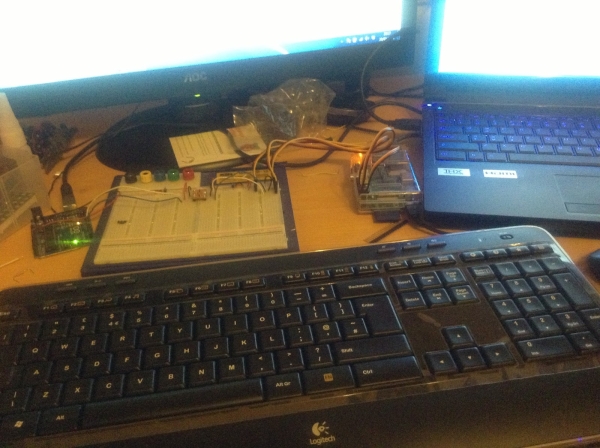
This is the circuit I built in photo form – very simple really. It's ultimatley just connecting the raspberry pi serial Rx/Tx to 2 pins on the arduino, however to avoid circuit damage there's a logic level converter in the middle.
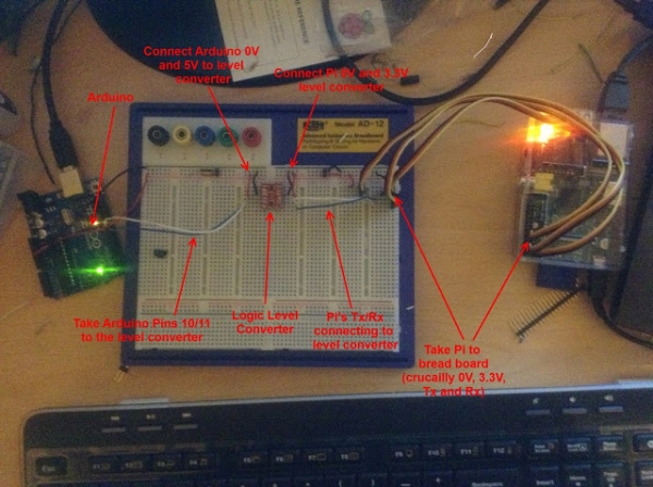
- Pin 1: 3.3V, connects to LV (low voltage) on the level converter
- Pin 6: 0V, connects to GND on level converter
- Pin 8: UART Tx, connects to Tx1 on level converter
- Pin 10: UART Rx, connects to Rx0 on level converter
- 5V goes to HV (high voltage) on the level converter
- GND goes to GND on level converter
- Pin 11 (using for software serial Tx) connects to Rx1 on level converter
- Pin 10 (using for software serial Rx) connects to Tx0 on level converter
I highly recommend testing the circuit with a voltmeter as you go. I verified the raspberry pi 0V/3.3V signals with a multimeter, and as you can see here.
For more detail: Raspberry Pi chats to Arduino