
Rev B of the raspberry Pi ships with a 26 pin GPIO port and my first dilemma after bringing up my Pi was, how was I going to break out the PI’s GPIO pins so that I could easily access them for design work? I searched on-line and found several solutions but all of them already did too much. I did not want someone else’s interface to their set of hardware and I did not want to use someone else’s buffer design. Then while searching through a drawer of parts, I had in my hand a solution – an old unused 40 pin IDE hard drive cable. I could plug one of the existing cable headers onto my Pi GPIO port and plug a custom header into my powered breadboard.
For more info. please visit http://www.raspberryproject.com/a-gpio-expansion-cable-from-a-used-hd-cable/.
Notes: There is some bad information floating around about the Raspberry Pi GPIO and a IDE cable.
1. Some people are claiming that using this cable will damage the GPIO port because per the IDE standard, some of the pins are shorted together. It's true that some of the pins are shorted together but this is at the IDE hardware & not in the cable. The cable is just wired straight through.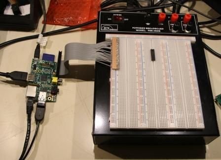
2. Some people are claiming that using this cable will damage the GPIO port because every second conductor is grounded. This is only true with the newer IDE standard that uses a 80 pin ribbon cable. A cable built under the older IDE standard is perfectly safe and it's easy to tell which one you have – just count the wires (ridges) in the cable. The cable you want to use will have only 40 wires, not 80 wires.
Step 1:
First you need to find a used IDE 40 pin hard drive cable. And it’s important that you use a 40 & not a 80 pin cable.
Step 2:
Cut the cable apart between the center connector & the connector on the shortest end & cut on the short cable side of the connector. I used an exacto knife but you can also use a good pair of scissors.
Step 3:
You should have a clean cut like this picture.
Step 4:
When done you should be able to spread the end out like this picture. You can also see where I cut off the other 14 wires I won’t need after figuring out which end of the cable will plug onto the GPIO header.
Step 5:
Because the connector is 40 pins and the Pi GPIO is 26 pins, you will have some overhang off the end of the board. You can’t cut the overhang off the end of the connector because if you do the connector will come apart.
Also, you should peel away & cut off the unused 14 ribbon conductors like I have shown above.
You can see here how the wires will map perfectly. GPIO pin 1 to the first wire, GPIO pin 2 to the second wire, etc.
Step 6:
For the header end I started with a Radio Shack P/N 276-170 board.
Step 7:
Look at the bottom of the board and you’ll see rows of 0.10″ spaced pads joined together. When assembled right, this makes the ideal single row header.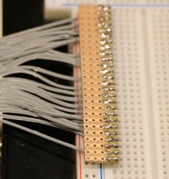
Step 8:
I cut the start of my custom header out of a section of this board. The cut out piece is 26 pins wide, just like the header pin count on the Pi
Step 9:
Then I inserted & soldered a header strip all the way down one side.
Step 10:
Here is a view of the solder side of the header strip.
Step 11:
Next step is to strip the ends of the ribbon cable wires.
For more detail: Raspberry Pi GPIO Expansion Cable from a Used IDE Cable