
In my house, you can often hear someone shouting “Is the Internet down?” Sometimes it is but most of the time it's a “user problem”. I decided to build a gizmo that would make it easy to tell whether the internet connection was working or not. Hence the Raspberry Pi Internet Monitor.
The Raspberry Pi Internet Monitor is used to provide visual status of a WiFi internet connection. A Raspberry Pi periodically issues Linux ping commands to a set of web sites and based on the results will illuminate different color lamps in an industrial tower lamp mounted on a laser cut case. If the pings are successful more than 50% percent of the time, the green lamp is illuminated (first photo). If the pings are successful 1 to 50% of the time, the amber lamp is illuminated (second photo). If the pings are unsuccessful, the red lamp is illuminated (third photo).
The Raspberry Pi Internet Monitor consists of a model B Raspberry Pi, a circuit for controlling the tower lamp, an illuminated switch used to indicate when the monitor is operational and gracefully shut down the Raspberry Pi when pressed, a barrier strip for connecting the circuit board to the tower lamp, and some jacks for connecting power as shown in the “Internet Monitor Wiring Diagram”. Two Python programs are used to monitor the internet connection and control the shutdown switch (for details on how these programs work see the last step of this instructable.)
The circuit for controlling the lamps uses opto-couplers connected in between the Raspberry PI's GPIO pins and the tower lamp. This is needed because the tower lamps require more voltage and current than the Raspberry Pi can deliver. The simple circuit used is shown in the “Internet Monitor Tower Light Controller Schematic”. The circuit is built on an Adafruit half-size perma-proto Raspberry Pi breadboard printed circuit board as shown in the “Internet Monitor Circuit Board Layout” diagram.
I made this at TechShop.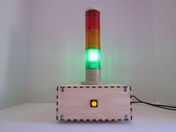
Step 1: Parts
The following parts and tools are needed to construct the Raspberry Pi Internet Monitor:
Raspberry Pi Parts:
- 1 Raspberry Pi model B 512MB RAM (Available from Amazon or Adafruit ID 998) (photo 1)
- 1 16GB SDHC class 4 card (8GB can also be used) (photo 2)
- 1 EDIMAX Wireless 802.11b/g/n nano USB Adapter (available from Amazon) or other supported WiFi adapter for Raspberry Pi (photo 3)
- 2 5/8″ #4-40 Machine screws and nuts (photo 4)
- 2 1/4″ Round nylon spacers for #4 machine screws (Amazon Supply part number B000FP9YW0) (photo 4)
- 2 #4 Flat nylon washers (Amazon Supply part number B000FN1560) (photo 4)
- 1 6″ USB Cable with male type A and male micro B connectors (Adafruit ID 898) (photo 5)
- 1 Neutrik NAUSB-W-B Reversible USB 2.0 gender changer (type A and B) (available from eBay) (photos 6 and 7)
- 2 #4-40 3/8″ flat head machine screws and nuts for the NAUSB-W-B (photo 8)
Tower Lamp Controller Circuit Board Parts:
- 1 Half-size Perma-Proto Raspberry Pi Breadboard PCB Kit (circuit board and GPIO socket) (Adafruit ID 1148) (photo 9)
- 1 GPIO Ribbon Cable for Raspberry Pi Model A and B – 26 pin 6″ (Adafruit ID 862) (photo 10)
- 3 1/4 watt 180 ohm resistors (photo 11)
- 1 LTV847 Quad Optocoupler (Jameco Part no. 878286) (photo 12)
- 1 16 Pin IC Socket (Jameco Part no. 37373) (photo 13)
- 1 Break-away 0.1″ male header (Adafruit ID 392) (photo 14)
- 1 DC Power Jack 2.1mm (Jameco Part no. 151555) (photos 15 and 16)
- 5 5/8″ #4-40 Machine screws and nuts (photo 17)
- 5 1/4″ Round nylon spacers for #4 machine screws (Amazon Supply part number B000FP9YW0) (photo 17)
- 5 #4 Flat nylon washers (Amazon Supply part number B000FN1560) (photo 17)
- 4 Spade tongue terminals for 16-22 AWG wires (Radio Shack 64-3031 or Jameco Part no. 842929) (photo 22)
- Heat shrink tubing (3/32″ diameter) (photo 23)
Industrial Tower Lamp Parts:
- 1 DC 12V Safety red yellow green industrial tower lamp (available from eBay) (photo 18)
- 3 #6-32 1/2″ Machine screws, nuts, and washers (photo 19) for mounting the tower lamp
- 1 4 Position connector barrier strip (similar to Jameco Part no. 230990) (photo 20)
- 2 1/2″ #6-32 Machine screws and nuts (photo 21) for mounting the barrier strip
- 4 Spade tongue terminals for 16-22 AWG wires (Radio Shack 64-3031 or Jameco Part no. 842929) (photo 22)
- Heat shrink tubing 3/32″ diameter (photo 23)
Shutdown Switch Parts:
- 1 16mm Illuminated push button red momentary switch (Adafruit ID 1439) (photo 24)
- 1 470 Ohm 1/4 watt resistor (photo 25)
- 4 12″ Jumper wires (one end male, one end female) (Sparkfun part number PRT-09385) (photo 26)
- Heat shrink tubing (1/16″ diameter) (photo 26)
Case Parts:
- 1 Sheet of 16″ x 16″ 1/8″ (3mm) birch plywood (not pictured)
- 24 #4-40 1/2″ Machine screws and nuts for holding the case together (photo 28)
- 4 Self adhesive rubber/plastic feet/bumpers (height 1/4″) (photo 29)
Power Supplies:
- 1 5 Volt 1 amp USB port power supply (Adafruit ID 501) (photo 30)
- 1 4 to 6 foot USB cable with a type B male connector and type A male connector (also called USB printer cables) (photo 31)
- 1 12 Volt 1 Amp Power Supply with Center Positive 2.1mm Connector (Jameco 1940774 or Adafruit ID 798) (photo 32)
Miscellaneous Parts:
- 18 AWG Wire (photo 33)
Tools (not pictured):
- Soldering iron and solder
- Heat source for heat shrink tubing (heat gun, matches, lighter, or candle)
- Wire cutters
- Wire strippers
- Small Philips head screw driver
- Small flat head screw driver
- Crimping Tool (Home Depot Store SKU # 131485 or Radio Shack catalog #: 6400225)
- Needle nose pliers
- 120 grade sandpaper (optional)
- Painter's tape (optional)
Equipment for installing Raspberry Pi software (not pictured):
- HDMI capable computer monitor
- USB keyboard
- USB mouse Ethernet cable
- Ethernet LAN connection to the Internet
Step 2: Cut the case parts with a laser cutter
The first step is to cut the parts for the case out of a sheet of 1/8″ (3mm) birch plywood. A 45 watt Epilog Helix laser cutter at TechShop was used to cut and engrave the parts. All of the case parts can be cut out from one 16″ x 16″ sheet of plywood.
The design is shown in the first diagram. The black lines will be cut by the laser cutter; the blue lines will be etched using a low power cutting setting; green text will be engraved; red lines will not be cut – they are included to show the outline of the parts. I used the color mapping capability of the Laser cutter to specify the settings for cutting and engraving. The setting used are shown in the right hand side of the “Color Mapping” screen capture.
The individual parts are:
- Bottom panel with mounting holes for the Raspberry Pi, circuit board, and barrier strip (photo 1)
- Top panel with mounting holes for the industrial tower lamp (photo 2)
- Side panel with cutout for Raspberry Pi LAN and USB ports (photo 3)
- Side panel with cutouts for the power plugs (photo 4)
- Side panel with the cutout for the shutdown switch (photo 5)
- Side panel with no cutouts (photo 6)
The burn marks left by the laser can be removed with a gentle sanding using 120 grit sandpaper.
The laser cutting design files are in the ZIP file attached to this step. The file contains CorelDraw X5 (.cdr) and Encapsulated PostScript (.eps) files for the design and the file for loading the color mapping data for the laser cutter. See page 113 of https://www.epiloglaser.com/downloads/pdf/mini_he… for details on how to use color mapping.
Note: Since I was not able to provide an exact part number for the barrier strip I used in this project, you may need to adjust the design slightly. Barrier strips vary in size and mounting hole position so before you laser cut the plywood, make sure that the mounting holes in the design file match your barrier strip.
Step 3: Setup the Raspberry Pi software
The first step in preparing the Raspberry Pi is to install and configure the Raspbian software:
- Download and load Raspbian (http://www.rasbian.com/RaspbianImages) onto a SD card. Instructions for how to do this can be found here (https://learn.adafruit.com/adafruit-raspberry-pi-lesson-1-preparing-and-sd-card-for-your-raspberry-pi/overview). I used the January 31, 2015 version of Raspbian: I would recommend using this version or a later one for this project: don't use an earlier version.
- Insert the SD card into the slot on the Raspberry Pi.
- Connect the Raspberry Pi to a display, keyboard, mouse, LAN with access to the internet, and a 5 volt USB power adapter as shown in the “Raspberry Pi Setup” diagram.
- Boot the Raspberry Pi and perform the first time configuration according to the instructions here (https://learn.adafruit.com/adafruits-raspberry-pi-lesson-2-first-time-configuration). When configuring Raspbian, do not configure the graphical user interface to start automatically. It's also a good idea to change the password for the Raspberry Pi at this time.
The second step is to download the Python programs that controls the shutdown switch and that monitors the internet connection. Create the directory where the Python programs will reside using these commands:
cd /home/pi
mkdir python_programs
cd python_programs
Issue the following two commands to get the Python programs:
wget "https://s3-us-west-1.amazonaws.com/talk2bruce/instructables/rpi-internet-monitor/rpi-halt-btn.py"
wget "https://s3-us-west-1.amazonaws.com/talk2bruce/instructables/rpi-internet-monitor/rpi-internet-monitor.py"
The third step is to configure the Raspberry Pi for use with your wireless network. Edit the file “wpa_supplicant.conf” with the command:
sudo nano /etc/wpa_supplicant/wpa_supplicant.conf
Add the following lines to the bottom of the file substituting the name of your wireless network and your wireless network's password as shown and save the file. If you are unfamiliar with how to use the nano editor, howtogeek has a nice Beginner's Guide to Nano.
network={
  ssid="my wifi network name"
  psk="my wifi password"
}
The file should look like the what is shown in screenshot 1. More details on how to configure the Raspberry Pi for different kinds of WiFi networks can be found on the Sparkfun website.
The fourth step is to configure the system to start the Python program that monitors and illuminates the shutdown button during the system boot process. Edit the file “rc.local” with the command:
sudo nano /etc/rc.local
Add the command below to the bottom of the file before the line that says “exit 0” and save the file.
python /home/pi/python_programs/rpi-halt-btn.py&
The file should look like the one in screenshot 2.
The fifth step is to configure the system to run the Python internet monitoring program when the WiFi on the Raspberry Pi is up and running. Once the Python internet monitoring program is running, it periodically tests the connection to the internet and will illuminate the appropriate lamp. The command to start the program is placed in the “/etc/network/interfaces” file. Edit the file with the command:
sudo nano /etc/network/interfaces
Add the following command to the bottom of the file:
post-up python /home/pi/python_programs/rpi-internet-monitor.py
The file should look like the one in screenshot 3.
Configuration of the Raspberry is now complete.
The last step is to shutdown the Raspberry Pi with the command:
sudo halt
After the Raspberry Pi shuts down, disconnect all the cables but leave the SD Card in the socket on the Raspberry Pi.
Step 4: Prepare wires for connecting to the tower lamp barrier strip
Cut four 7″ lengths of wire (photo 1).
Strip 1/4″ of wire from one end of each wire, place a spade tongue terminal on the stripped end of each wire and crimp the terminal using a crimping tool (photo 2 and 3).
Step 5: Attach spade tongue terminals to tower lamp wires
Strip 1/4″ of insulation off the ends of each of the wires (photo 2)
Using a soldering iron “tin” the end of the wires by applying the tip of your iron to each of the wires for a second or two, then touching the solder to the wire. The solder should flow freely onto the wire and in to the strands, coating it (photo 3).
Cut 1/4″ of 3/32″ diameter heat shrink tubing for each of the wires and slide the heat shrink tubing onto the wires (photo 4). The heat shrink tubing is very important: the wires from the tower lamp are very thin and the heat shrink tubing will add strength to prevent the wires from breaking off the spade tongue terminals.
Place a spade tongue terminal on the end of each wire and crimp the terminal using a crimping tool (photo 5).
Slide the heat shrink tubing over each of the ends of the spade tongue terminals and using a heat source (heat gun, matches, lighter, or candle) shrink the tubing (photos 6 and 7).
Step 6: Prepare the power jack
Cut two 1/4″ lengths of 1/16″ heat shrink tubing (photo 1).
Cut two 6″ lengths of wire, strip both ends and solder one end of each to the inner terminals on the power jacks (photo 2). Make sure to connect the red wire to the center terminal.
Slide the heat shrink tubing onto the wires and move over the inner terminals (photo 3).
Use a heat source(heat gun, matches, lighter, or candle), shrink the tubing over the terminals (photo 4).
Step 7: Prepare the shutdown switch
Using the following parts: push button switch (photo 1), jumper wires (photo 2), 470 ohm resistor (photo 3), and heat shrink tubing (photo 4), prepare the switch:
Cut four lengths of 1/16″ heat shrink tubing (photo 5).
Cut off the male ends of the jumper wires (photo 6).
Strip the ends off the wires (photo 7). Slide the heat shrink tubing onto the wires (photo 8).
Using photo 9 as a guide to the terminals on the switch, solder the resistor to the positive (+) terminal (photo 10).
Attach and solder the red wire to the resistor (photos 11 and 12).
Cutoff the excess wire on the resistor.
Attach and solder the black wire to the negative (-) terminal (photos 13 and 14) using photo 9 as a guide.
Attach and solder the blue wires to the remaining terminals (photo 15).
Slide the heat shrink tubing over the resistor and over the exposed wires soldered to the terminals (photo 16).
Use a heat source (heat gun, lighter, candle, or match) to shrink the tubing.
The completed switch is shown in photo 17.
Step 8: Assemble and solder the circuit board
The circuit board is used to isolate the the Raspberry Pi from the higher voltage used by the tower lamp. The diagram shows the wiring for circuit board and the connections to Raspberry Pi and tower lamp.
Solder the components to the circuit board as follows (before soldering double check to make sure you have the components in the correct holes):
Using the diagram and photos 1 and 2 as guides, cut and solder wires as shown, solder the resistors in place, and then solder the GPIO connector and IC socket to the board. Make sure the notch on the GPIO connector and the notch on the IC socket are pointing in the same way as in the diagram and the photos.
Strip the ends of the wires prepared in step 4 of this instructable and solder to the board as illustrated in photos 3 and 4.
Solder the wires from the power jack prepared in step 6 of this instructable to the board as shown in photo 5.
Carefully insert the LTV847 Quad Optocoupler into the IC socket (photos 6 and 7).
Break off 4 of the headers from the Break-away 0.1″ male header strip (photo 8).
Solder the header strip to the circuit board (photo 9).
Step 9: Connect the components
Attach the Raspberry Pi to the circuit board using the GPIO ribbon cable (photos 2 to 6).
Attach the four wires with the spade tongue connectors to the barrier strip (photos 6 to 8).
Step 10: Attach the shutdown switch to the case
Remove the fastener ring from the switch (photo 1).
Insert the switch through the hole in the shutdown switch side panel (photo 2).
Slide the fastener ring over the wires with jagged edge facing the side panel and screw onto the switch (photo 3).
Before tightening the fastener ring, use the engraved lines on the outside of the panel as guides to make sure the switch is not crooked (photo 4).
Tighten the fastener ring to hold the switch firmly in place (photo 5).
Step 11: Prepare USB power connector and attach it to the case
Disassemble the NAUSB-W-B Reversible USB 2.0 gender changer (photos 1 and 2) by removing the screws (photo 3).
Reassemble the USB gender changer with the Type B plug facing outwards and the Type A plug on the inside (photos 4 and 5).
Use two #4-40 3/8″ flat head machine screws and nuts (photo 6) to attach the gender changer to the side panel as shown in photos 7 to 10.
Step 12: Attach the Raspberry Pi to the bottom panel
Using the 5/8″ #4-40 machine screws, the 1/4″ round nylon spacers, the #4 flat nylon washers, and the #4 nuts (photo 1), attach the Raspberry Pi to the bottom panel as follows:
Insert the two screws from the bottom (you can use painter's tape to hold them in position if your hands are not large enough to keep a finger on each screw head) (photo 2).
Place a nylon spacer on each screw (photo 3).
Place the Raspberry Pi onto the screws (photo 4).
Place a nylon washer onto each of the screws (photo 5).
Screw a nut onto each of the screws and tighten enough to hold the board firmly in place (photo 6). Don't over tighten the screws.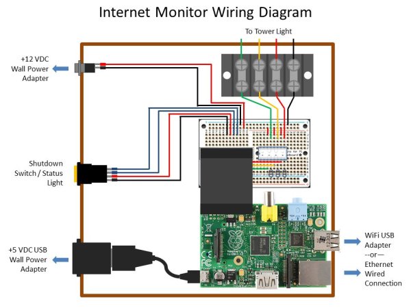
Step 13: Attach the circuit board to the bottom panel
Using the 5/8″ #4-40 machine screws, the 1/4″ #4 round nylon spacers, the #4 flat nylon washers, and the #4 nuts (photo 1), attach the circuit board to the bottom panel as follows:
Insert the five screws from the bottom (you can use painter's tape to hold them in position if your hands are not large enough to keep a finger on each screw head) (photo 2).
Place a nylon spacer on each screw (photo 3).
Place the circuit board onto the screws (photo 4).
Place a nylon washer onto each of the screws (photo 5).
Screw a nut onto each of the screws and tighten enough to hold the board firmly in place (photo 6). Don't over tighten the screws.
Step 14: Attach the barrier strip to the bottom panel
Use two 1/2″ #6-32 machine screws and nuts (photo 1) to attach the barrier strip to the bottom panel (photo 2) as shown in photos 3 to 5.
For more detail: Raspberry Pi Internet Monitor