
To simplify using the the MCP23017 I/O Expander on the Raspberry Pi I’ve made a little plug in board using a Slice of Pi from Ciseco. The Slice of Pi is a handy little PCB that plugs directly onto the Raspberry Pi’s GPIO pins and gives a convenient row of labelled standard 0.1 inch (2.54mm) headers for the built in GPIO, SPI and I2C pins, a small prototyping area and optionally headers for plugging in an XBee style wireless devices such as the XRF, XBee, RN-XV etc. It’s not expensive at £3.90 plus postage either. (Update 27/7/12 – Ciseco are now doing an MCP23017 specific board called the Slice of PI/O, here is a comparison of the two)
I’ve fitted a 28 pin DIL socket to it for the MCP23017 and connected power and the SCL and SDA pins from the Pi as well as the required lines to switch it on and set the I2C address (fixed to 0x20). I’ve also added two sets of 0.1″ headers for the 16 I/O pins.
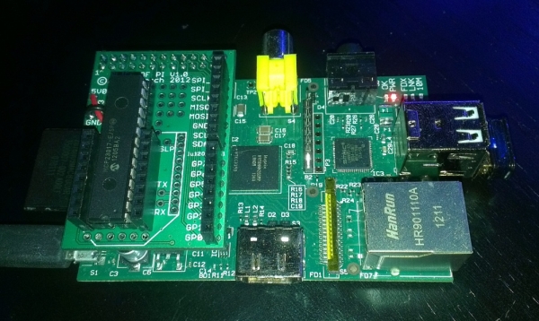 The result is a simple plug in expander board that can provide up to 16 inputs or outputs that can sink or source up to 25mA each, more than the 16mA of the Pi’s own GPIO pins and safer, the MCP23017 costs less than £1 and if you do accidentally blow it up and can just be popped out and a new one popped in. Along with the Python tools I’m working on I’m hoping this will be useful to help provide a simple, low cost and relatively safe way for people to experiment with connecting other hardware to the Raspberry Pi.
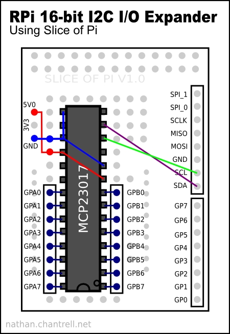
Here’s the layout of the board and the required connections as well as pictures of the front and back of the finished board:
Note: Make sure pins 15,16,17 of the MCP23017 all connected to ground (the 3 pins top left of the diagram, shown linked in blue).
Using it
I’ve tried to make this a simple step by step guide but I didn’t take notes when doing it so it has been done from memory, please let me know if I’ve left anything out or if something isn’t clear.
To use this you will need a Raspberry Pi with the Debian Squeeze distro and a kernel that supports I2C. Update 28/7/12: If you are using the new Raspbian image this is much easier and doesn’t need a replacement kernel, see the instructions in this comment below.
You can get the source for a suitable kernel here or you can use one that I’ve already compiled by copying this kernel.img to /boot and extract this modules tar.gz file to /lib/modules/eg.
wget http://nathan.chantrell.net/downloads/raspberry_pi/3.2.18+/kernel.img
wget http://nathan.chantrell.net/downloads/raspberry_pi/3.2.18+/3.2.18+_modules.tar.gz
sudo chown root:root kernel.img
sudo mv kernel.img /boot/
tar zxvf 3.2.18+_modules.tar.gz
sudo chown -R root:root 3.2.18+
sudo mv 3.2.18+ /lib/modules/
To get the I2C device driver to load on boot you will need to edit /etc/modules and add new line containing i2c-dev. Otherwise you can do sudo modprobe i2c-dev to load it manually each time you boot the Pi.
Reboot now so that you are using the new kernel and install the i2c-tools package with:
sudo apt-get install i2c-tools
To give your regular user account permission to use the expander add it to the i2c group with:
sudo adduser your-userid i2c
and you should now be able to do i2cdetect -y 0 (use i2cdetect -y 1 if you have one of the new revision 2 Raspberry Pis with mounting holes and marked as made in the UK) and see the expander is located at address 0x20 as below:
nsc@raspberrypi:~$ i2cdetect -y 0
     0  1  2  3  4  5  6  7  8  9  a  b  c  d  e  f
00:          -- -- -- -- -- -- -- -- -- -- -- -- --
10: -- -- -- -- -- -- -- -- -- -- -- -- -- -- -- --
20: 20 -- -- -- -- -- -- -- -- -- -- -- -- -- -- --
30: -- -- -- -- -- -- -- -- -- -- -- -- -- -- -- --
40: -- -- -- -- -- -- -- -- -- -- -- -- -- -- -- --
50: -- -- -- -- -- -- -- -- -- -- -- -- -- -- -- --
60: -- -- -- -- -- -- -- -- -- -- -- -- -- -- -- --
70: -- -- -- -- -- -- -- --
A previous post explained how you can go on to use i2c-tools to control the MCP23017 or read on to find out how you can use the Python tools I’m working on. So far they are only working for output but I plan on extended them to cover input as well.
Command Line Tool
To use my Python command line tool you will need to install the python-smbus python module with:
sudo apt-get install python-smbus
then download my script and make it executable with: chmod +x mcp23017.py
Note: If you are using one of the new revision 2 Raspberry Pis you will need to change the line bus = smbus.SMBus(0) to bus = smbus.SMBus(1)
To test it connect an LED with the cathode (short leg) to ground and the anode (long leg) connected via a resistor to the port marked GPA0 in the diagram above. To calculate the resistor required for your LED see this page or if you don’t know the resistors specification a 220 Ohm resistor should be safe for a 3mm or 5mm LED.
and then try the following to make GPA0 high (ie. 5v) and turn the LED on:
./mcp23017.py -b a -o 0 -s high
you should get a response of “Output GPA0 changed to high” and the LED will turn on. To turn it off:
./mcp23017.py -b a -o 0 -s low
For more detail: Raspberry Pi I O Expander Board