
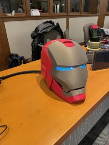
For my final project I decided to create an Iron Man Helmet with dual motors and a transparent OLED “Heads Down” Display powered by a Raspberry Pi with an Adafruit Crickit Hat. I wanted to do my own take on how I would create an operational Iron Man helmet. I downloaded the files and design for the helmet from Thingiverse, link with credits below, but the rest of the work is my own design and approach to tackling this project. I hope you enjoy!
Supplies
- 3D Printed Parts
- Raspberry Pi (I used a Raspberry Pi 4 as I had one on hand)
- Adafruit Crickit Hat
- SparkFun Transparent OLED Screen
- 2x DC Motor in Micro Servo Body
- Battery Pack for Crickit Hat
- 2 M2x6 screws
- 2 M3x8 screws with nuts
- LED Lights for light up eyes
- Wires and wire stripper
- Soldering equipment
Step 1: Print All Parts for the Helmet
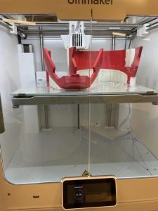
First step is to 3D print all the parts to make the helmet. I was fortunate enough to be able to use my university's Ultimaker S5 as it was the only printer that was big enough to print everything. The total print time took just over 4 days. I printed all the parts in PETG using a .20mm layer height with support everywhere.
You want to print all the files attached here. Make sure to print the Ear piece twice as well as 4 hinge arms.
Step 2: Assemble the Helmet
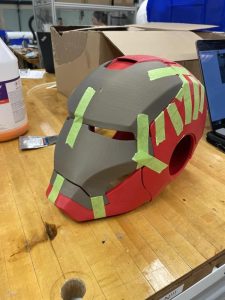
Next you are going to want to assemble the helmet into three separate parts. Pictured you can see me using tape to make sure all parts fit together nicely. Do this following the instructions below:
- Glue the mouth and chin pieces together to form the first part
- Glue the Face_Up and Face_Down pieces together to complete the mask part.
- Finally, glue the Up and Down pieces together to form the helmet body. We will add the Ears in later.
Step 3: Add Components to the Inside of the Face Mask
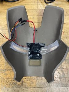
Now we want to wire up and add all the components that will live on the inside of the face mask. For this step you are going to want to get your glued together face mask, transparent OLED, and LED's for the light up eyes. The LED's for the eyes that I linked above come hooked up to a battery back with an on/off switch. For this project we are going to want to cut off the battery back and strip the ends of both wires, we will connect them to the Raspberry Pi in order to control when they turn on and off. I used a super glue to attach each eye into the inside of the face over the eye holes. Then, I used electrical tape to flatten the two wires (red and black) to guide them straight up the mask towards the top. After adding in the eyes, you want to add in the OLED screen. Before putting the OLED on the inside of the mask, connect the 4-pin cable to the OLED board and leave the wires hanging out, we will connect them later. BE CAREFUL with the OLED as the one ribbon cable connecting it to its board is quite fragile. Carefully place the board above the eyes in the middle and bend the ribbon cable over the wires for the eyes and tape everything down. Make sure the 4 cables are sticking out the side for later. For reference you can see my picture above with what it should look like after you everything is in place.
Step 4: Add Motors and Hinges to the Helmet Body
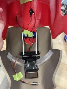
Next, grab the big helmet body piece and your two DC motors. Glue them side by side on the middle part sticking out (as pictured above). Next glue the FaceMount piece to the face mask right above the tape from your wiring in the previous step. You can pull the LED eye wires underneath this part to guide them to the top of the mask. After you glue that down, grab two of your hinge arms, 2 M3 screws and nuts and 2 M2 screws. Use the M2 screws to attach a hinge arm to each motor by screwing into each gear. Use the M3 screws to attach the other side of the hinge arm to the FaceMount piece that is now glued to the inside of the mask. use the picture above for reference on how it should look.
Step 5: Extend All Wires So They Can Reach Out the Back of the Helmet
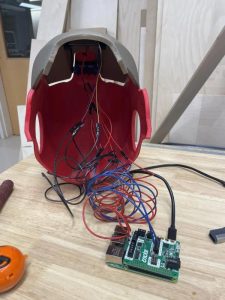
We want to extend EVERY wire now about 3-4 feet, or long enough so they can go along the top inside of the helmet and out the back. I did this by cutting and stripping wire, twisting them together, and then using heat shrink or electrical tape to secure them.
Step 6: Attach Wires to Cricket Hat and Raspberry Pi
Now it is time to attach all wires to their specific destinations. This step is crucial to get right otherwise the code will not work! First, attach the Cricket Hat to the Raspberry Pi by clicking it into all the pins. Next, take the two wires that you extended from each motor and find the Motor 1 and Motor 2 inputs on the Crickit Hat. Plug each motor into either Motor 1 or Motor 2, it also does not matter which input red or black goes into as long as each motor is either in motor 1 or motor 2 terminal. Use a small flathead screwdriver to tighten the terminal and secure the wires to the Crickit Hat. Next, find the LED wires for the lights. There should be two wires that you extended, one of them black and one of them red. Locate the Signal I/O Pins on the Crickit. Plug the red one into Signal 1 and the black one into ground one. Finally, you should have 4 more wires to connect. These last four wires belong to the OLED. We will connect them to the Raspberry Pi by creating a QWiiC connection using the Pi's I2C bus. I2C is a serial connection bus that many micro controllers have. This is how we will communicate with the OLED. Start by finding the red and black wires and plug the red one into any 3.3v pin on the Crickit Signal I/O's and then plug the black one into any of the Ground pins on the Crickit Signal I/O's. We could solder these to a 3.3v and ground pin on the Pi itself but this makes it a little bit easier and less soldering. Finally we have two cables left, Blue and Yellow from the OLED screen. The blue wire represents the SDA connection and the yellow represents the SCL connection. Attach each to their corresponding pin on the Raspberry Pi by soldering them onto the Crickit Hat.
Step 7: Time to Code!
Now it is time to upload the code for the project! I will be doing this by using ssh to access my Raspberry Pi as well as using an smb connection to upload files to my Raspberry Pi, instructions that I used on how to set up smb can be found here. The code file is attached below and I heavily commented in order to provide detail into what each function does. At the moment, each time the code is run (using the command python3 helmet.py) the helmet will open for seconds and then close. Also, the OLED display will be active and displaying the current date, time, and location that it gets from the internet.
Step 8: Testing Out Code and Motors
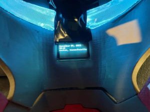
Now we want to run the code using the command python3 helmet.py on our Raspberry Pi. This way we will be able to test out the motors, lights, and OLED screen. A video above shows how the motors should lift up the face mask, turn the eyes off while the mask is up, and then close the mask and turn the eyes back on. An image above shows how the inside of the helmet should look with both they eyes lit up and the custom “heads down” display operates.
Step 9: Attach Chin and Mouth Piece to Helmet
This step can be done in multiple different ways using different materials. I decided to use two more hinges to do this but could also use magnets to attach it. The reason it is not glued onto the helmet body is because the helmet will not be able to fit over your head with the chin piece attached. This was quite annoying to figure out and delicate operation. Definitely an aspect of this project that I want to approve upon in the near future… as well as adding the JARVIS software update.
Source: Raspberry Pi Iron Man Helmet With “Heads Down” Display