
Topic Discussion Overview
- Installation from scratch
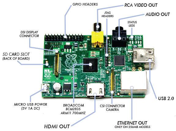
- Hardware Pin Out
- Raspberry Pi, HelloWorld for I/O pins
- Understanding UART, SPI, I2C port on Raspberry Pi
- Networking on Raspberry Pi
- Accessing Raspberry Pi through the network
- C Programming
- Python Programming
- Java Programming
- List of frequent used Commands
- Add Wifi to Raspberry Pi
STEP 01:
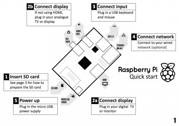
Download this quick start up guide to help you install your Linux OS on your Raspberry Pi.
STEP 02:
Get yourself a 4GB SD card, which is enough for use in many application.
NOTE: Not all SD cards work with the Raspberry Pi. High speed cards can be too fast for the Raspberry Pi bus. Check out which SD card is suitable for your Raspberry Pi. It has a lists of cards that have and have not worked for Raspberry Pi users. http://elinux.org/RPi_SD_cards
You may also like to check out the various peripherals that are compatiable to Raspberry Pi.
http://elinux.org/RPi_VerifiedPeripherals
| STEP 03:
Format your SD card with SD Formatter 4.0 for SD/SDHC/SDXC
|
|||||
| STEP 04:
You can download the image version New Out Of Box Software (NOOBS), extract all the files and copy into your SD card. Insert this SD card into your Raspberry Pi, and power on it. Follow the instruction on your screen display to complete the installation process.
|
|||||
| STEP 05:
You will be ask to select an Linux OS to install on your Raspberry Pi. Choose the recommended “Raspian”, which is also the Raspbian “wheezy”. The installation process will proceed.
Proceed to ste
|
STEP 10:
On the first boot, the “raspi-config” menu will pop up.
STEP 11:
Select <1> and press enter to Expand Filesystem.
If you are connected to the network, select <8 Advanced Options> and press enter.
<A2 Hostname> to change the hostname default “raspberrypi”.
<A3 Memory Split> to configure the amount of ram allocation for GPU (graphic processing).
<A4 SSH> to enable or disable SSH (remote command access); it is enable by default.
<A5 Update> and then press enter to upgrade to the latest version of this tool. Try to perform this update.
To change to the Standard US Keyboard mapping, select <4 Internationalisation Options>,
<I1 Change Locale>, with the following options,
Default Locale : None
<I2 Time Zone >, with the following options,
Geographic area: Asia
Time Zone : Singapore
<I3>, with the following options,
Keyboard model : “Generic 105-key (Intl) PC”
Keyboard layout: “Others” -> “English (US)”
AltGr as : “The default for the keyboard layout”
Compose Key : “No compose key”
Ctrl+Alt+Backsp: “No”, (don't use it to terminate Xserver)
You can also configure to allow the system to boot directly straight into the GUI desktop, using this raspi-config.
Select <Finish> then press enter to proceed to the system command shell.
You can always come back to this raspi-config menu again by executing the command “sudo raspi-config” from the shell command.
Very Very Important Note regarding boot up error
If you have encounter any error during the Linux operating system boot up, be sure to check the voltage level being supplied to your Raspberry Pi. It is a very common problem faced, if you have tried to power up your Raspberry Pi using any power adaptor that you have picked up.
Always check if your power adaptor is suitable by measuring the voltage supplied to your Raspberry Pi. If you deploy your Raspberry Pi for yoru project without ensuring that your power adaptor is ok, you may face random system error freeze/hang/halt. Problem can occur out of the norm. Be sure to check. Click here to find out how you can ensure that you are using the correct power adaptor and cable for your Raspberry Pi.
| 2. Hardware Pin Out | |||||||||||||||||||||||||||||||||||||||||||||||||||||||||||||||||||||||||||||||||||||||||||||||||||||||||
Raspberry Pi revision 2, header pins out.
Information taken from
|
|||||||||||||||||||||||||||||||||||||||||||||||||||||||||||||||||||||||||||||||||||||||||||||||||||||||||
| 4. Understanding UART, SPI, I2C port on Raspberry Pi | |
| UART
The UART port is actually pin8 (TxD) and pin10 (RxD) on the Raspberry Pi connectors. The UART signal is 3.3V.You can use RS232/RS422/RS485 communication to talk to the UART, but a level shifter (for example MAX3232) required. RS232 uses about +/- 7 to 13V, while UART uses digital voltage (1.8V, 3.3V or 5V). For our Raspberry Pi UART, it is 3.3V. More information about making your own level shifter, you can visit this page. There are also standard USB to UART products for interfacing to your Raspberry Pi.The Raspberry Pi default operating system uses this UART port as its diagnostic port. This port has the following default UART settings, |
|
| You can use a terminal program to access through this port.Using the Window's Hyperterminal program, setup the correct com port settings. And connect the terminal. You will see nothing on the terminal screen, but actually the Raspberry Pi is prompting you for your login ID. This ID is “pi” which is similar to how you log on to your typical terminal screen. You will see the terminal replying you with the prompt for password. Key in the default password “raspberry”. You shall get a similar print out from the terminal program, as on the right. ->Looks very much like the typical terminal on your local display. This is mainly for troubleshooting, diagnostic or perhaps used for remote access of your Raspberry Pi.
|
raspberrypi login: pi Password: Last login: Wed Jun 19 15:36:44 UTC 2013 on tty1 Linux raspberrypi 3.6.11+ #474 PREEMPT Thu Jun 13 17:14:42 BST 2013 armv6lThe programs included with the Debian GNU/Linux system are free software; the exact distribution terms for each program are described in the individual files in /usr/share/doc/*/copyright.Debian GNU/Linux comes with ABSOLUTELY NO WARRANTY, to the extent permitted by applicable law. pi@raspberrypi:~$ |
| The UART on the Raspberry Pi is quite an useful peripheral. For me, I would like to use this UART as a serial communication to control my other circuit modular.
In order to use this UART, I need to disable the diagnostic features from the operating system's boot up. This means that I do not want the system to setup the UART pins as diagnotic port, when the system boots up. |
|
| This means that we need to edit the boot up file. Before we do any editing, it is good to save a backup copy of it. Type the copy command “cp” as follows. -> | pi@raspberrypi ~ $ sudo cp /boot/cmdline.txt /boot/cmdline_backup.txt |
| The following command is key in to edit the system boot up script. vi is an text editor program, which is not very user friendly.Alternative, you can use nano editor instead of vi for the text file editing. Or gedit editor. You can install then if they are not installed. “sudo apt-get install nano” or “sudo apt-get install gedit ” To learn how to use the vi editor, click on the following link, http://www.unix-manuals.com/tutorials/vi/vi-in-10-1.htmlA summary of the vi editor's command is summeries as follows, http://osr600doc.sco.com/en/FD_create/vi_summary.html |
pi@raspberrypi ~ $ sudo vi /boot/cmdline.txt |
| After the vi command, you should see the following screen display. This is the vi editor diaplaying the text in the “cmdline.txt file”.The objective is to delete the text (in red color), which is relating to the UART setup. Press ‘l' on your keyboard to shift the cursor to the right, until it is at the position of the char that we want to delete. Move the cursor under the first char ‘c‘ (char as illustrated in red).Press ‘x' on your keyboard to delete the char one by one. You should observed the delete action.When all the text in red are deleted, press ‘:w' on your keyboard, follow by a enter key to save the text file.Press ‘:q' on your keyboard, follow by a enter key to exit the vi program.If at anytime you have edit wrongly, you can enter the command ‘:q!' on your keyboard, to exit the vi program without saving the text file.
|
dwc_otg.lpm_enable=0 console=ttyAMA0,115200 kgdboc=ttyAMA0,115200 console=tty1 root=/dev/mmcblk0p2 rootfstype=ext4 elevator=deadline rootwait ~ ~ ~ ~ ~ ~ |
| Your “cmdline.txt” should contain the following text after the editing. | dwc_otg.lpm_enable=0 console=tty1 root=/dev/mmcblk0p2 rootfstype=ext4 elevator=deadline rootwait ~ ~ ~ |
| Next edit inittab with the following command. | pi@raspberrypi ~ $ sudo vi /etc/inittab |
| Find and comment away the line containing the following text (near the end of the file), “T0:23:respawn:/sbin/getty -L ttyAMA0 115200 vt100”, by pressing the ‘j' on your keyboard to scroll down line by line.Issue an insert command by pressing ‘i' to insert some text before the cursor. Insert a char ‘#‘ at the beginning of the line to comment the whole line. The ‘#' mask off the whole line. The line that are masked off will not be intepreted by the system.After the ‘#' char is inserted, press <Esc> key on your keyboard to end the insert command that was issued.Press ‘:w' save the text file.Press ‘:q' to exit the vi program. |
#Spawn a getty on Raspberry Pi serial line #T0:23:respawn:/sbin/getty -L ttyAMA0 115200 vt100 |
| The UART device name is /dev/ttyAMA0 Now the UART is not in use by the Linux Raspbian operating system, and is available for my own use. |
|
| Reboot for the operating system's settings to take effect. | pi@raspberrypi ~ $ sudo reboot |
| To test the UART serial communication port, we can install a program call minicom. The use of minicom is similar to hyperterminal program that I use in Windows operating system (OS).
Enter the command “sudo apt-get install minicom“ There are also alternative GUI based serial communication program, cutecom. |
pi@raspberrypi ~ $ sudo apt-get install minicom
Reading package lists… Done |
| To run the minicom terminal program. Key in the following command “sudo minicom -b 9600 -o -D /dev/ttyAMA0“.
-o (skip initialisation) Key in command “man minicom” to find out the other options that you can set with the minicom program. Configuration Settings: Apply the configuration settings to serial port “ttyAMA0”. The label tty (known as teletype) denotes all serial communication that the linux operating system is handling. In Raspberry Pi, ttyAMA0 refers to the pin8 (TxD) and pin10 (RxD). When you type a char on your keyboard, an ascii char code is actually sent out of the Raspberry Pi ‘s pin8 (TxD). You will not be able to see it on the screen. What you will see on your screen will be those serial data that the Raspberry Pi received through pin10, which is the RxD. In order to see what we have transmitted out from TxD, we can short the pin8 (TxD) and pin10 (RxD) together. This means that what you send will be receive and display on the display. The serial port configuration for the TxD and RxD is the same, so the serial data that is received will be exactly what you have transmitted. The following text “Hello World!!! ” were typed on the keyboard after shorting the RxD and Txd pin. The text will be displayed, indicating that the UART is working properly. Now that you know that the UART on your Raspberry Pi is ready for use, you can use it to communicate with many other peripheral. Press <Ctrl + ‘A'>, followed by <‘X'>, then key in enter for “Yes” to quit the minicom program. |
pi@raspberrypi ~ $ sudo minicom -b 9600 -o -D /dev/ttyAMA0
——————————————- CTRL-A Z for help | 9600 8N1 | NOR | Minicom 2.6.1 | VT102 | Offline |
| Setting up the serial port with other settings, Baudrate : 115200bps Data bit : 8 Stop bits: 1 Parity : Even
|
pi@raspberrypi ~ $ sudo minicom -b 115200 -8 -o -D /dev/ttyAMA0 |
| Key in command “sudo minicom -s ” to launch the minicom menu for other default settings, which can be save onto *.dfl files. The default config file is minicom.dfl |
|
| Other related commands
– “dmesg | grep tty” checking up the UART available on the system. |
|
| SPI
The SPI port onboard the Raspberry is disable by default. The first thing to do is to enable the SPI port. Edit the file “/etc/modprobe.d/raspi-blacklist.conf“ Comment off the line “blacklist spi-bcm2708” with a # in front. Key in Ctrl+'X' to exit, then ‘Y' yes to save the change to the file, and finally ‘Enter'. This will brings you back to the command prompt. |
pi@raspberrypi ~ $ sudo nano /etc/modprobe.d/raspi-blacklist.conf
GNU nano 2.2.6 File: /etc/modprobe.d/raspi-blacklist.conf Modified # blacklist spi and i2c by default (many users don't need them) #blacklist spi-bcm2708
|
| Reboot Raspberry Pi | pi@raspberrypi ~ $ sudo reboot |
| Check to see if the SPI is successfully enable in the Raspberry Pi.
You should see “/dev/spidev0.0 /dev/spidev0.1″ created. 0.0 means SPI0 CS0 (CS is the chip select) |
pi@raspberrypi ~ $ ls /dev/spidev* /dev/spidev0.0 /dev/spidev0.1 pi@raspberrypi ~ $ |
| Testing the SPI port
download this SPI loopback test code written in ‘C' programming language. Compile the *.c file using gcc command,then run the compiled program. You should see the following hex dump data, indicating all 0x00. This means that the SPI is receiving nothing, no data. |
pi@raspberrypi ~ $ gcc spidev_test.c -o spidev_test pi@raspberrypi ~ $ sudo ./spidev_test -D /dev/spidev0.0 spi mode: 0 bits per word: 8 max speed: 500000 Hz (500 KHz)00 00 00 00 00 00 00 00 00 00 00 00 00 00 00 00 00 00 00 00 00 00 00 00 00 00 00 00 00 00 00 00 00 00 00 00 00 00 pi@raspberrypi ~ $ |
| Now we do a SPI data loopback test. Short the pins MISO (GPIO 9, Pin21) and MOSI (GPIO 10, Pin19) on your Raspberry Pie. This will enables the SPI MISO to received whatever data that is sent out from the MOSI pins.From this test, we will be able to know if SPI hardware for sending and receving is working ok. Whatever that is sent out, the data should be properly received. Run the compiled program again.You should see the following hex dump data. This means that your SPI peripheral is working fine.
|
pi@raspberrypi ~ $ sudo ./spidev_test -D /dev/spidev0.0 spi mode: 0 bits per word: 8 max speed: 500000 Hz (500 KHz)FF FF FF FF FF FF 40 00 00 00 00 95 FF FF FF FF FF FF FF FF FF FF FF FF FF FF FF FF FF FF DE AD BE EF BA AD F0 0D pi@raspberrypi ~ $ |
| I2C
The SPI port onboard the Raspberry is disable by default. The first thing to do is to enable the SPI port. Edit the file “/etc/modprobe.d/raspi-blacklist.conf“ Comment off the line “blacklist i2c-bcm2708” with a # in front. Key in Ctrl+'X' to exit, then ‘Y' yes to save the change to the file, and finally ‘Enter'. This will brings you back to the command prompt. |
pi@raspberrypi ~ $ sudo nano /etc/modprobe.d/raspi-blacklist.conf
GNU nano 2.2.6 File: /etc/modprobe.d/raspi-blacklist.conf Modified # blacklist spi and i2c by default (many users don't need them) blacklist spi-bcm2708
|
| Edit the file “/etc/modules“
Add in “i2c-dev” to the end of the file. Key in Ctrl+'X' to exit, then ‘Y' yes to save the change to the file, and finally ‘Enter'. This will brings you back to the command prompt. |
pi@raspberrypi ~ $ sudo nano /etc/modules
# /etc/modules: kernel modules to load at boot time. snd-bcm2835
|
| Install I2C Tools to test on the I2C peripheral. | pi@raspberrypi ~ $ sudo apt-get install i2c-tools Reading package lists… Done Building dependency tree Reading state information… Done Suggested packages: libi2c-dev python-smbus The following NEW packages will be installed: i2c-tools 0 upgraded, 1 newly installed, 0 to remove and 52 not upgraded. Need to get 59.5 kB of archives. After this operation, 223 kB of additional disk space will be used. Get:1 http://http.debian.net/debian/ wheezy/main i2c-tools armel 3.1.0-2 [59.5 kB] Fetched 59.5 kB in 4s (12.5 kB/s) Selecting previously unselected package i2c-tools. (Reading database … 57047 files and directories currently installed.) Unpacking i2c-tools (from …/i2c-tools_3.1.0-2_armel.deb) … Processing triggers for man-db … Setting up i2c-tools (3.1.0-2) … |
| Allow Pi User to Access I2C peripheral.
This allow configuration of the software. |
pi@raspberrypi ~ $ sudo adduser pi i2c Adding user `pi' to group `i2c' … Adding user pi to group i2c Done. |
| Reboot Raspberry Pi | pi@raspberrypi ~ $ sudo reboot |
| Check to see if the SPI is successfully enable in the Raspberry Pi.
You should see “/dev/i2c-0 /dev/i2c-1″ created. |
pi@raspberrypi ~ $ ls /dev/i2c* /dev/i2c-0 /dev/i2c-1 pi@raspberrypi ~ $ |
| Running the test program.
You will see that there is a total of 0x77 or 119 blanks “–“. This indicates that no I2C devices is detected on the bus. |
pi@raspberrypi ~ $ i2cdetect -y 0 0 1 2 3 4 5 6 7 8 9 a b c d e f 00: — — — — — — — — — — — — — — — — 10: — — — — — — — — — — — — — — — — 20: — — — — — — — — — — — — — — — — 30: — — — — — — — — — — — — — — — — 40: — — — — — — — — — — — — — — — — 50: — — — — — — — — — — — — — — — — 60: — — — — — — — — — — — — — — — — 70: — — — — — — — — |
| If the I2C devices is on the I2C bus, it will appeared as follows. For this example, the I2C devices has an address of 0x60. The software detects a device is currently onto the I2C data bus. |
For more detail: Raspberry Pi (low level I/O electronics control)