
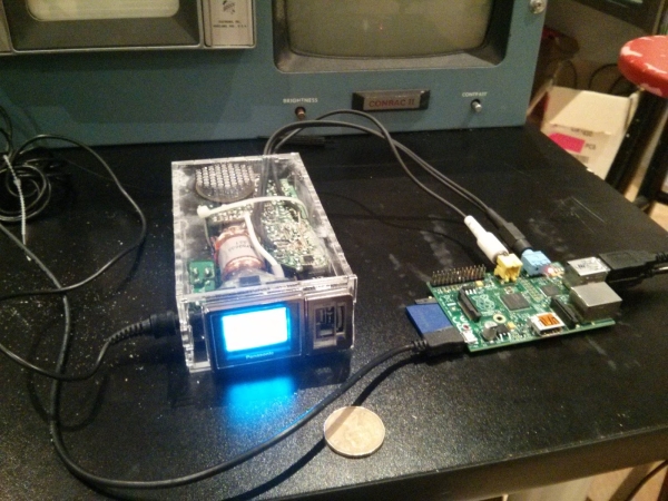
Last week at hacklab.to, my friend Igor brought in a Panasonic TR-1030P. This is a black and white CRT, with an astonishingly small 35mm (1.37″) screen diagonal, circa 1984. A great find for $5 at Value Village.
A good set of teardown pictures can be found here.
Designed to receive NTSC over VHF and UHF, this television is no longer relevant where we live since August 31 2011, when Canada stopped broadcasting NTSC, and instead only digital ATSC. The TV has no other inputs, yet happily displayed static when turned on. I figured we could easily inject a composite signal somewhere on the board and get it to work – the question was where.
Yes, we knew before we started that we could just use an RF modulator and hooked that to the antenna. To me, that takes away the fun and the challenge. Then I wouldn't have learned anything!
We took it apart, and looked at the obvious major components – Antenna and RF can, tuner (channel) knob, yoke drive, and HV power supply – to get a sense of the layout. Due to being portable, the circuit board is folded onto a rectangular prism, meaning large portions aren't accessible! The teardown pictures listed above were quite useful in getting chip IDs, from which we were able to find all the old Panasonic datasheets.
 Using the block diagram of an analog monochrome CRT, above, we wanted to find the “Composite video” signal (because that's what we have!) between the demodulator and the Video Amplifier/Sync Separator.
The sync separator chip was easily located, because it was hooked to the yoke drive circuitry. The yoke is the set of electromagnets wound around the CRT which direct the electron beam vertically and horizontally.
We tried injecting composite from a VHS player onto the input of the sync separator, and were rewarded by the chip correctly outputting sync pulses. The display stabilized a bit too, but naturally it was still showing static.
The antenna and RF can led us to the IF amplifier section, near the VHF/UHF selector switch, used to access channels above 13. However it wasn't initially clear where the IF amplifier outputs went, nor where the inputs of the sync separator came from. I don't even remember if we ended up finding the video amplifier.
However the teardown pictures came to the rescue. One of the inaccessible chips was marked C80580 – somehow Igor managed to track down the IC this came from, an AN5715 “low voltage video IF signal and sound signal processing” chip. How he managed this is beyond me, because I couldn't replicate the feat.
[Edit: Igor tells me that he noticed the pattern that every chip in this television set is from Panasonic, and starts with “AN5”. Lookup through the datasheet for every chip he could find with this combination, he narrowed it down by package shape and pin count. Neat!]
A good set of teardown pictures can be found here.Designed to receive NTSC over VHF and UHF, this television is no longer relevant where we live since August 31 2011, when Canada stopped broadcasting NTSC, and instead only digital ATSC. The TV has no other inputs, yet happily displayed static when turned on. I figured we could easily inject a composite signal somewhere on the board and get it to work – the question was where.
Yes, we knew before we started that we could just use an RF modulator and hooked that to the antenna. To me, that takes away the fun and the challenge. Then I wouldn't have learned anythinge
The sync separator chip was easily located, because it was hooked to the yoke drive circuitry. The yoke is the set of electromagnets wound around the CRT which direct the electron beam vertically and horizontally.We tried injecting composite from a VHS player onto the input of the sync separator, and were rewarded by the chip correctly outputting sync pulses. The display stabilized a bit too, but naturally it was still showing static.
The antenna and RF can led us to the IF amplifier section, near the VHF/UHF selector switch, used to access channels above 13. However it wasn't initially clear where the IF amplifier outputs went, nor where the inputs of the sync separator came from. I don't even remember if we ended up finding the video amplifier.
However the teardown pictures came to the rescue. One of the inaccessible chips was marked C80580 – somehow Igor managed to track down the IC this came from, an AN5715 “low voltage video IF signal and sound signal processing” chip. How he managed this is beyond me, because I couldn't replicate the feat.
[Edit: Igor tells me that he noticed the pattern that every chip in this television set is from Panasonic, and starts with “AN5”. Lookup through the datasheet for every chip he could find with this combination, he narrowed it down by package shape and pin count. Neat!]
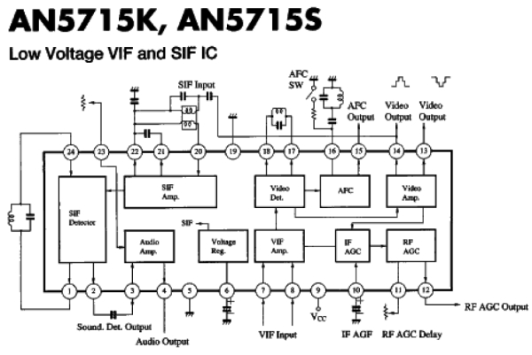 Now we're getting somewhere. The chip takes VIF input – this is an Intermediate Frequency signal, from the IF section. It produces several outputs, but the most relevant is pins 13 and 14 – the video output pins. From my research, typically there is only one video line; why this chip has two is beyond me.
We tried injecting composite onto either pin 13 or 14, and neither seemed to work correctly. I build a signal inverter with an NPN BJT and attempted to drive both, with little success. We managed to get the TV syncing, which gave us a flat grey image. This was exciting! Finally we changed something. We packed up for the night, and planned to continue hacking on this at Hacklab's booth at the 2014 Mini Maker Faire here in Toronto.
During the faire, my goal was to amplify the composite signal the Pi was putting out, only around 0.5Vpp instead of the unofficial standard of 1Vpp. This really got us nowhere because I've learned it's hard to build useful circuits in a space not much larger than your breadboard, and no place to sit. I replicated two composite video amplifier circuits I found online, and neither seemed to work correctly. Perhaps I can attribute that to the fact that I had no composite video to test with – someone accidentally packed the wrong Raspberry Pi, one without a composite output. I was using the oscilloscope's 1kHz signal with a voltage divider instead.