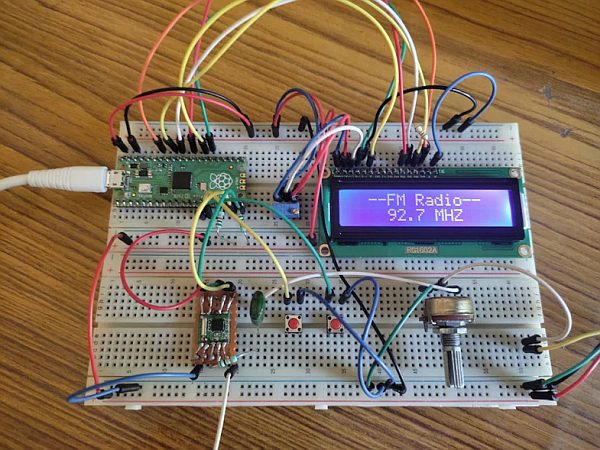
In this Instructables we are going to make a FM radio receiver using raspberry pi pico and TEA5767 FM receiver chip. Here I am using micropython programming language to program the Raspberry pi pico. let’s get started!
Supplies
List of hardware:
- Raspberry pi pico
- TEA5767 FM receiver chip
- HD44780 LCD (16*2, blue back color)
- Pushbutton
- PAM8403 Class-D Stereo power amplifier module
- Bread board–2
- Jumper wires
- Resistors (1K—2, 10K—1, 100–1)
- Capacitors (0.1UF)
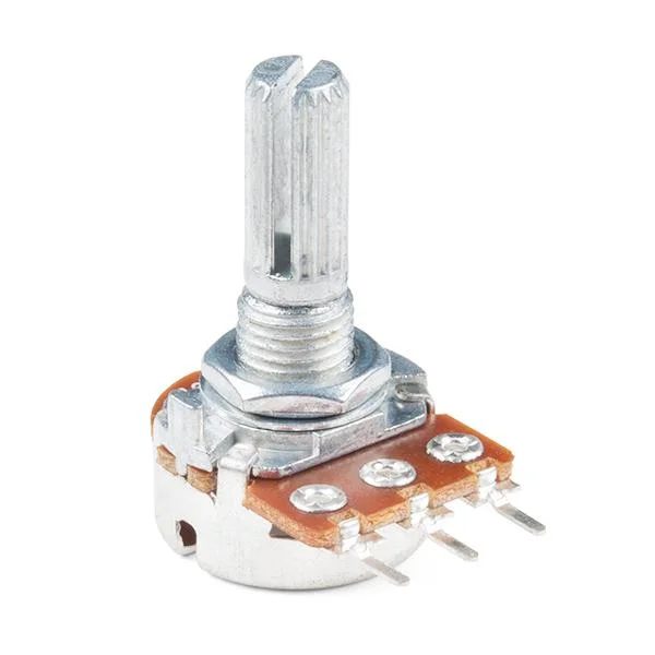
- Potentiometer (10K)
- Multiturn potentiometer(10K)
- Speaker (4-ohm, 3W)
- Micro-B USB cable
Step 1: Connecting LCD to Pico Board
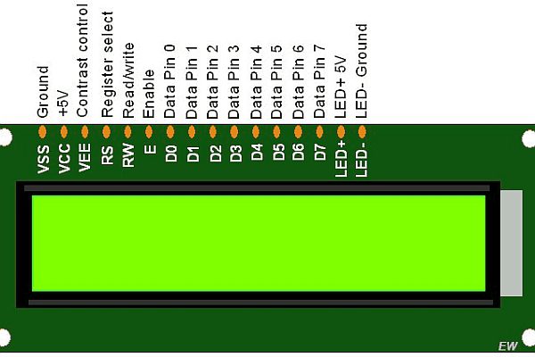
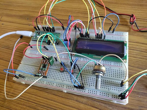
Join both the bread board to each other. Insert the Raspberry pi pico board and LCD in the upper bread board as shown in the diagram. Connect the Pins of the LCD to Raspberry pi pico according to given wiring scheme:
RS ——> GPIO-21
E ——-> GPIO-22
D4 ——> GPIO-23
D5 ——> GPIO-26
D6 —–> GPIO-27
D7 ——> GPIO-28
A ——-> To the positive supply rail of the upper bread board in series with a 100-ohm current limiting resistor to limit the current of backlight LED of the LCD
K ——-> To the negative supply rail of the upper bread board
Vss —–> To the negative supply rail of the upper bread board
Vdd —-> To the positive supply rail of the upper bread board
Vo —–> TO the viper pin of the 10K potentiometer
R/W —-> To the negative supply rail of the bread board
D0 ——-> Not used
D1 ——> Not used
D2 —-> Not used
D3 —–> Not used
Connect the remaining pins of the 10K Potentiometer to the negative and positive supply rail of upper bread board respectively. This 10K potentiometer is used to adjust the contrast of the characters of the display.
Step 2: Connecting TEA5767 to Pico Board

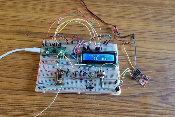
Insert the TEA5767 breakout board to the lower breadboard as shown in the picture. Connect the pins of TEA5767 breakout board according to the given wiring scheme:
SDA —–> GPIO-14
SCL ——> GPIO-15
Vcc ——> To the positive supply rail of the upper bread board
GND ——> To the negative supply rail of lower bread board
L-OUT —-> T0 the 0.1UF capacitor in series with a 10K Resistor
Antenna —–> TO a long jumper wire
Also connect the SDA and SCL pins of the TEA5767 To the Positive supply rail of the bread board through two 1K resistor. These two resistors are called pull up resistors and almost always used with all I2C devices. If you don’t use the two resistors then the system will not work and you will get some error during running the program on the Raspberry pi pico.
Step 3: Connecting Amplifier Board and Loudspeaker
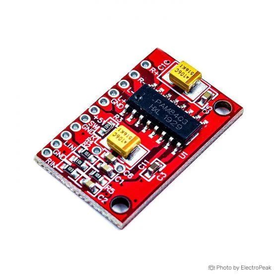
PAM8403 is a stereo class-D power amplifier so it has two amplifier channels for left and right speakers, but here I am going to use only the Left channel. Connect the pins of the PAM8403 according to the given wiring scheme.
Vcc ——-> To the positive supply rail of the lower breadboard
GND ——> To the negative supply rail of the lower brad board
L-OUT+ —–> To the positive pin of the Loudspeaker
L-OUT- —–> To the negative pin of the loudspeaker
L-IN —–> To the viper pin or middle pin of 10K potentiometer
Step 4: Connecting Potentiometer

Insert the 10K potentiometer to the lower breadboard as given in the picture. Connect the pins of 10K potentiometer according to the given wiring scheme:
Left-pin ——-> To the negative supply rail of lower bread board
Right-Pin ——-> To 0.1UP capacitor
Middle-Pin ——-> To the L-IN pin of the PAM8403 Board
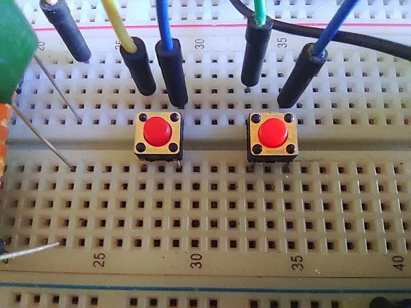
Insert two pushbuttons in the middle of the lower bread board and connect their pins according the given wiring scheme.
Left-Pin —–> GPIO-10
Right-Pin —–> To negative supply rail of lower bread board
Left-Pin ——> GPIO-10
Right-Pin ——-> To the negative supply rail of lower bread board
Here all the wiring of the hardware is done. It is also necessary to recheck all the connections twice to check out all the connections are right ad tight.
Step 6: Rechecking All Wiring Connections
After rechecking all the wiring connections, connect the Raspberry pi pico to Laptop or computer and open the Thonny on the system. Now go to tools and then choose options and a new box will open as shown in the image. Here in the first section, you have to choose the micropython (Raspberry pi pico) and in the second option we have to choose the COM port on which our pi pico board is connected to and clink on OK. Now your pico will connect to Thonny.
Note – If you have any doubt about it then check my “Raspberry pi pico” Instructables to get rid of any connectivity problem.
Step 7: Programming (python Modules and Main File)
First open a new file in Thonny and paste the following python code and save the file in lib folder in Raspberry pi pico with the name ‘gpio_lcd.py’.
"""Implements a HD44780 character LCD connected via ESP32 GPIO pins."""

from lcd_api import LcdApi
from machine import Pin
from utime import sleep_ms, sleep_us


class GpioLcd(LcdApi):
  """Implements a HD44780 character LCD connected via ESP32 GPIO pins."""

  def __init__(self, rs_pin, enable_pin, d0_pin=None, d1_pin=None,
         d2_pin=None, d3_pin=None, d4_pin=None, d5_pin=None,
         d6_pin=None, d7_pin=None, rw_pin=None, backlight_pin=None,
         num_lines=2, num_columns=16):
    """Constructs the GpioLcd object. All of the arguments must be machine.Pin
    objects which describe which pin the given line from the LCD is
    connected to.

    When used in 4-bit mode, only D4, D5, D6, and D7 are physically
    connected to the LCD panel. This function allows you call it like
    GpioLcd(rs, enable, D4, D5, D6, D7) and it will interpret that as
    if you had actually called:
    GpioLcd(rs, enable, d4=D4, d5=D5, d6=D6, d7=D7)

    The enable 8-bit mode, you need pass d0 through d7.

    The rw pin isn't used by this library, but if you specify it, then
    it will be set low.
    """
    self.rs_pin = rs_pin
    self.enable_pin = enable_pin
    self.rw_pin = rw_pin
    self.backlight_pin = backlight_pin
    self._4bit = True
    if d4_pin and d5_pin and d6_pin and d7_pin:
      self.d0_pin = d0_pin
      self.d1_pin = d1_pin
      self.d2_pin = d2_pin
      self.d3_pin = d3_pin
      self.d4_pin = d4_pin
      self.d5_pin = d5_pin
      self.d6_pin = d6_pin
      self.d7_pin = d7_pin
      if self.d0_pin and self.d1_pin and self.d2_pin and self.d3_pin:
        self._4bit = False
    else:
      # This is really 4-bit mode, and the 4 data pins were just
      # passed as the first 4 arguments, so we switch things around.
      self.d0_pin = None
      self.d1_pin = None
      self.d2_pin = None
      self.d3_pin = None
      self.d4_pin = d0_pin
      self.d5_pin = d1_pin
      self.d6_pin = d2_pin
      self.d7_pin = d3_pin
    self.rs_pin.init(Pin.OUT)
    self.rs_pin.value(0)
    if self.rw_pin:
      self.rw_pin.init(Pin.OUT)
      self.rw_pin.value(0)
    self.enable_pin.init(Pin.OUT)
    self.enable_pin.value(0)
    self.d4_pin.init(Pin.OUT)
    self.d5_pin.init(Pin.OUT)
    self.d6_pin.init(Pin.OUT)
    self.d7_pin.init(Pin.OUT)
    self.d4_pin.value(0)
    self.d5_pin.value(0)
    self.d6_pin.value(0)
    self.d7_pin.value(0)
    if not self._4bit:
      self.d0_pin.init(Pin.OUT)
      self.d1_pin.init(Pin.OUT)
      self.d2_pin.init(Pin.OUT)
      self.d3_pin.init(Pin.OUT)
      self.d0_pin.value(0)
      self.d1_pin.value(0)
      self.d2_pin.value(0)
      self.d3_pin.value(0)
    if self.backlight_pin is not None:
      self.backlight_pin.init(Pin.OUT)
      self.backlight_pin.value(0)

    # See about splitting this into begin

    sleep_ms(20)  # Allow LCD time to powerup
    # Send reset 3 times
    self.hal_write_init_nibble(self.LCD_FUNCTION_RESET)
    sleep_ms(5)  # need to delay at least 4.1 msec
    self.hal_write_init_nibble(self.LCD_FUNCTION_RESET)
    sleep_ms(1)
    self.hal_write_init_nibble(self.LCD_FUNCTION_RESET)
    sleep_ms(1)
    cmd = self.LCD_FUNCTION
    if not self._4bit:
      cmd |= self.LCD_FUNCTION_8BIT
    self.hal_write_init_nibble(cmd)
    sleep_ms(1)
    LcdApi.__init__(self, num_lines, num_columns)
    if num_lines > 1:
      cmd |= self.LCD_FUNCTION_2LINES
    self.hal_write_command(cmd)

  def hal_pulse_enable(self):
    """Pulse the enable line high, and then low again."""
    self.enable_pin.value(0)
    sleep_us(1)
    self.enable_pin.value(1)
    sleep_us(1)    # Enable pulse needs to be > 450 nsec
    self.enable_pin.value(0)
    sleep_us(100)   # Commands need > 37us to settle

  def hal_write_init_nibble(self, nibble):
    """Writes an initialization nibble to the LCD.

    This particular function is only used during initialization.
    """
    self.hal_write_4bits(nibble >> 4)

  def hal_backlight_on(self):
    """Allows the hal layer to turn the backlight on."""
    if self.backlight_pin:
      self.backlight_pin.value(1)

  def hal_backlight_off(self):
    """Allows the hal layer to turn the backlight off."""
    if self.backlight_pin:
      self.backlight_pin.value(0)

  def hal_write_command(self, cmd):
    """Writes a command to the LCD.

    Data is latched on the falling edge of E.
    """
    self.rs_pin.value(0)
    self.hal_write_8bits(cmd)
    if cmd <= 3:
      # The home and clear commands require a worst
      # case delay of 4.1 msec
      sleep_ms(5)

  def hal_write_data(self, data):
    """Write data to the LCD."""
    self.rs_pin.value(1)
    self.hal_write_8bits(data)

  def hal_write_8bits(self, value):
    """Writes 8 bits of data to the LCD."""
    if self.rw_pin:
      self.rw_pin.value(0)
    if self._4bit:
      self.hal_write_4bits(value >> 4)
      self.hal_write_4bits(value)
    else:
      self.d3_pin.value(value & 0x08)
      self.d2_pin.value(value & 0x04)
      self.d1_pin.value(value & 0x02)
      self.d0_pin.value(value & 0x01)
      self.hal_write_4bits(value >> 4)

  def hal_write_4bits(self, nibble):
    """Writes 4 bits of data to the LCD."""
    self.d7_pin.value(nibble & 0x08)
    self.d6_pin.value(nibble & 0x04)
    self.d5_pin.value(nibble & 0x02)
    self.d4_pin.value(nibble & 0x01)
    self.hal_pulse_enable()
open a new file in Thonny again and copy the following python code and save it in the lib folder in raspberry pi pico with file name’ lcd_api.py’.
"""Provides an API for talking to HD44780 compatible character LCDs."""

import time

class LcdApi:
  """Implements the API for talking with HD44780 compatible character LCDs.
  This class only knows what commands to send to the LCD, and not how to get
  them to the LCD.

  It is expected that a derived class will implement the hal_xxx functions.
  """

  # The following constant names were lifted from the avrlib lcd.h
  # header file, however, I changed the definitions from bit numbers
  # to bit masks.
  #
  # HD44780 LCD controller command set

  LCD_CLR = 0x01       # DB0: clear display
  LCD_HOME = 0x02       # DB1: return to home position

  LCD_ENTRY_MODE = 0x04    # DB2: set entry mode
  LCD_ENTRY_INC = 0x02    # --DB1: increment
  LCD_ENTRY_SHIFT = 0x01   # --DB0: shift

  LCD_ON_CTRL = 0x08     # DB3: turn lcd/cursor on
  LCD_ON_DISPLAY = 0x04    # --DB2: turn display on
  LCD_ON_CURSOR = 0x02    # --DB1: turn cursor on
  LCD_ON_BLINK = 0x01     # --DB0: blinking cursor

  LCD_MOVE = 0x10       # DB4: move cursor/display
  LCD_MOVE_DISP = 0x08    # --DB3: move display (0-> move cursor)
  LCD_MOVE_RIGHT = 0x04    # --DB2: move right (0-> left)

  LCD_FUNCTION = 0x20     # DB5: function set
  LCD_FUNCTION_8BIT = 0x10  # --DB4: set 8BIT mode (0->4BIT mode)
  LCD_FUNCTION_2LINES = 0x08 # --DB3: two lines (0->one line)
  LCD_FUNCTION_10DOTS = 0x04 # --DB2: 5x10 font (0->5x7 font)
  LCD_FUNCTION_RESET = 0x30  # See "Initializing by Instruction" section

  LCD_CGRAM = 0x40      # DB6: set CG RAM address
  LCD_DDRAM = 0x80      # DB7: set DD RAM address

  LCD_RS_CMD = 0
  LCD_RS_DATA = 1

  LCD_RW_WRITE = 0
  LCD_RW_READ = 1

  def __init__(self, num_lines, num_columns):
    self.num_lines = num_lines
    if self.num_lines > 4:
      self.num_lines = 4
    self.num_columns = num_columns
    if self.num_columns > 40:
      self.num_columns = 40
    self.cursor_x = 0
    self.cursor_y = 0
    self.implied_newline = False
    self.backlight = True
    self.display_off()
    self.backlight_on()
    self.clear()
    self.hal_write_command(self.LCD_ENTRY_MODE | self.LCD_ENTRY_INC)
    self.hide_cursor()
    self.display_on()

  def clear(self):
    """Clears the LCD display and moves the cursor to the top left
    corner.
    """
    self.hal_write_command(self.LCD_CLR)
    self.hal_write_command(self.LCD_HOME)
    self.cursor_x = 0
    self.cursor_y = 0

  def show_cursor(self):
    """Causes the cursor to be made visible."""
    self.hal_write_command(self.LCD_ON_CTRL | self.LCD_ON_DISPLAY |
                self.LCD_ON_CURSOR)

  def hide_cursor(self):
    """Causes the cursor to be hidden."""
    self.hal_write_command(self.LCD_ON_CTRL | self.LCD_ON_DISPLAY)

  def blink_cursor_on(self):
    """Turns on the cursor, and makes it blink."""
    self.hal_write_command(self.LCD_ON_CTRL | self.LCD_ON_DISPLAY |
                self.LCD_ON_CURSOR | self.LCD_ON_BLINK)

  def blink_cursor_off(self):
    """Turns on the cursor, and makes it no blink (i.e. be solid)."""
    self.hal_write_command(self.LCD_ON_CTRL | self.LCD_ON_DISPLAY |
                self.LCD_ON_CURSOR)

  def display_on(self):
    """Turns on (i.e. unblanks) the LCD."""
    self.hal_write_command(self.LCD_ON_CTRL | self.LCD_ON_DISPLAY)

  def display_off(self):
    """Turns off (i.e. blanks) the LCD."""
    self.hal_write_command(self.LCD_ON_CTRL)

  def backlight_on(self):
    """Turns the backlight on.

    This isn't really an LCD command, but some modules have backlight
    controls, so this allows the hal to pass through the command.
    """
    self.backlight = True
    self.hal_backlight_on()

  def backlight_off(self):
    """Turns the backlight off.

    This isn't really an LCD command, but some modules have backlight
    controls, so this allows the hal to pass through the command.
    """
    self.backlight = False
    self.hal_backlight_off()

  def move_to(self, cursor_x, cursor_y):
    """Moves the cursor position to the indicated position. The cursor
    position is zero based (i.e. cursor_x == 0 indicates first column).
    """
    self.cursor_x = cursor_x
    self.cursor_y = cursor_y
    addr = cursor_x & 0x3f
    if cursor_y & 1:
      addr += 0x40  # Lines 1 & 3 add 0x40
    if cursor_y & 2:  # Lines 2 & 3 add number of columns
      addr += self.num_columns
    self.hal_write_command(self.LCD_DDRAM | addr)

  def putchar(self, char):
    """Writes the indicated character to the LCD at the current cursor
    position, and advances the cursor by one position.
    """
    if char == '\n':
      if self.implied_newline:
        # self.implied_newline means we advanced due to a wraparound,
        # so if we get a newline right after that we ignore it.
        pass
      else:
        self.cursor_x = self.num_columns
    else:
      self.hal_write_data(ord(char))
      self.cursor_x += 1
    if self.cursor_x >= self.num_columns:
      self.cursor_x = 0
      self.cursor_y += 1
      self.implied_newline = (char != '\n')
    if self.cursor_y >= self.num_lines:
      self.cursor_y = 0
    self.move_to(self.cursor_x, self.cursor_y)

  def putstr(self, string):
    """Write the indicated string to the LCD at the current cursor
    position and advances the cursor position appropriately.
    """
    for char in string:
      self.putchar(char)

  def custom_char(self, location, charmap):
    """Write a character to one of the 8 CGRAM locations, available
    as chr(0) through chr(7).
    """
    location &= 0x7
    self.hal_write_command(self.LCD_CGRAM | (location << 3))
    self.hal_sleep_us(40)
    for i in range(8):
      self.hal_write_data(charmap[i])
      self.hal_sleep_us(40)
    self.move_to(self.cursor_x, self.cursor_y)

  def hal_backlight_on(self):
    """Allows the hal layer to turn the backlight on.

    If desired, a derived HAL class will implement this function.
    """
    pass

  def hal_backlight_off(self):
    """Allows the hal layer to turn the backlight off.

    If desired, a derived HAL class will implement this function.
    """
    pass

  def hal_write_command(self, cmd):
    """Write a command to the LCD.

    It is expected that a derived HAL class will implement this
    function.
    """
    raise NotImplementedError

  def hal_write_data(self, data):
    """Write data to the LCD.

    It is expected that a derived HAL class will implement this
    function.
    """
    raise NotImplementedError

  def hal_sleep_us(self, usecs):
    """Sleep for some time (given in microseconds)."""
    time.sleep_us(usecs)
Now again open a new file in Thonny and paste the following code in this file and then save it in the Raspberry pi pico with file name ‘main.py’.
from machine import Pin, I2C
from gpio_lcd import GpioLcd
import time

push1 = Pin(10, Pin.IN, Pin.PULL_UP)
push2 = Pin(11, Pin.IN, Pin.PULL_UP)

frec = 92.7
frec1 = 92
frec2 = 7
std1 = 1
std2 = 1

i2c = I2C(1,scl=Pin(15), sda=Pin(14), freq=400000)
lcd = GpioLcd(rs_pin=Pin(20),
       enable_pin=Pin(21),
       d4_pin=Pin(22),
       d5_pin=Pin(26),
       d6_pin=Pin(27),
       d7_pin=Pin(28),
       num_lines=2, num_columns=16)

lcd.move_to(2,0)
lcd.putstr('--FM Radio--')
time.sleep_ms(10)

def radio_frequency(freq):
  freqB = 4 * (freq * 1000000 + 225000) / 32768
  buf = bytearray(5)
  buf[0] = int(freqB) >> 8
  buf[1] = int(freqB) & 0XFF
  buf[2] = 0X90
  buf[3] = 0X1E
  buf[4] = 0X00
  i2c.writeto(0x60, buf)
  time.sleep_ms(10)

def print_frequency(freq1, freq2):
  lcd.move_to(4,1)
  str_freq = str(freq1) + "." + str(freq2) + " MHZ "
  lcd.putstr(str_freq)
  time.sleep_ms(10)

radio_frequency(frec)
print_frequency(frec1,frec2)

while True:

  if push1.value() == 0:
    time.sleep_ms(10)
    if push1.value() == 0:
      std1 = 0
      time.sleep_ms(10)
  if push1.value() == 1 and std1 == 0:
    frec2 = frec2 + 1
    if frec2 > 9:
      frec1 = frec1 + 1
      frec2 = 0
    if frec1 == 108 and frec2==1:
      frec1 = 88
      frec2 = 0
    frec = frec1 + (frec2/10)
    radio_frequency(frec)
    print_frequency(frec1,frec2)
    std1 = 1

  if push2.value() == 0:
    time.sleep_ms(10)
    if push2.value() == 0:
      std2 = 0
      time.sleep_ms(10)
  if push2.value() == 1 and std2 == 0:
    frec2 = frec2 - 1
    if frec2 < 0:
      frec1 = frec1 - 1
      frec2 = 9
    if frec1 == 87 and frec2 == 9:
      frec1 = 108
      frec2 = 0
    frec = frec1 + (frec2/10)
    radio_frequency(frec)
    print_frequency(frec1,frec2)
    std2 = 1
now click on run option and radio starts, you can listen your favorite FM radio stations now.
all the above micro python files are also available on my GitHub account visit the link:
https://github.com/ramjipatel041/Raspberrypipico_radio.git