
Build a live train departure display for your desk with a Raspberry Pi Zero W and OLED screen.
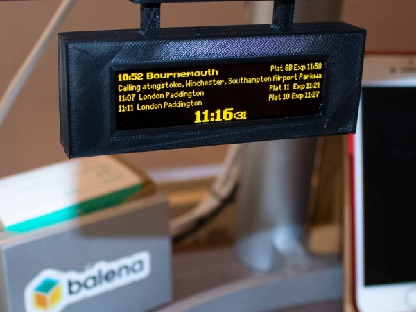
Build your own UK train station platform departure display (next train indicator) with live data using a Raspberry Pi Zero, OLED display and 3D-printed case – a cool (and practical!) desktop gadget. It involves a bit of software, a bit of soldering, and some 3D printing, too.
Introduction
A while back I came across this tweet by Chris Hutchinson, he’d started a project to pull data from Transport API and display live train departure information on a small OLED display to mimic those signs seen on station platforms in the UK.
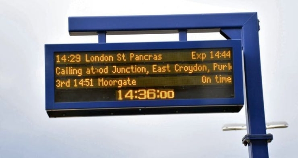
I really liked his work so decided to build my own and make some changes along the way, notably to change the software setup to run in Docker on balenaCloud to make it easy to deploy and configure. Additionally, I reworked the display layout to achieve 1:1 pixel mapping of the fonts and avoid any scaling in order to look more like the dot-matrix LED displays of the real thing.
I’m all done and really happy with the result so this is just a quick writeup to document the process and enable you to build your own. If you do build one I would love to hear about it!
Hardware required
The hardware requirements for this project are minimal, this is what you’re going to need.
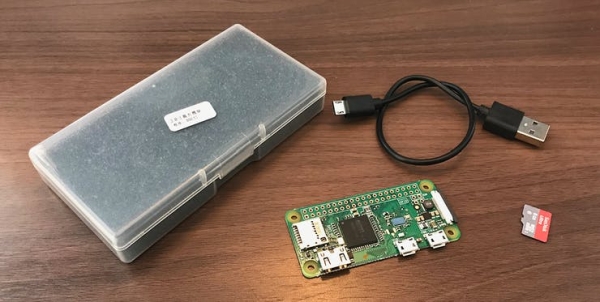
- Raspberry Pi Zero W – I used the version without headers in order to fit it into a smaller case, but others will work too
- SD card – 8GB is plenty
- USB cable (for power)
- SSD1322 OLED display – I used this 2.8” one in yellow from AliExpress
- And, if you want to print your own case, a 3D printer or 3D printing service.
Software required
The project has been built to run in a Docker container on balenaCloud; this means you can deploy the project with only a couple of steps, saving any time-consuming manual package installation or configuration. So you’ll need:
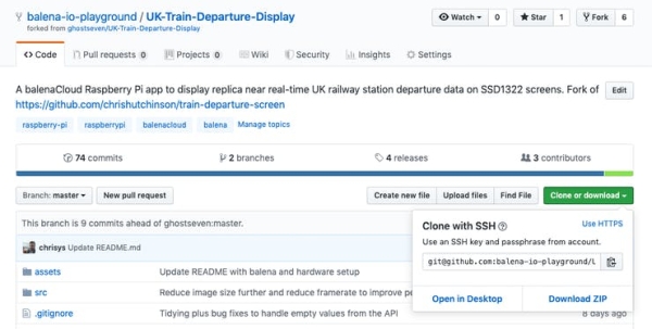
- A download of the project from GitHub
- Software to flash an SD card (balenaEtcher)
- A free balenaCloud account to setup and manage the PiDownload and install the balena CLI tools – to be installed on your computer, allowing you to install the project code on the Pi
Putting it together
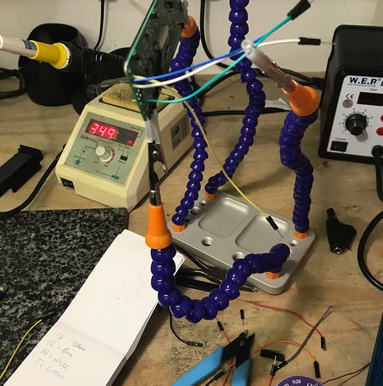
The first task is to connect the display to the GPIO header on your Raspberry Pi. I used a Raspberry Pi Zero W which is supplied without pin headers, this meant that I was able to fit it in a much smaller space, but does mean I had to solder wiring to the Pi. Note: if you’re using my case design you’ll have to solder the wires to the Pi after the display is inserted into the case.
I’ve included the pinout below which is for the 2.8” display that I got from AliExpress. Other SSD1322 (or even other controllers) based displays will probably work fine, you just need to be a bit careful of the pinouts and double-check that they’re correct before powering on.
Note: Some displays have a solder-blob or zero-ohm resistor jumper on the back of the board that you may need to move in order to enable the display for SPI communication. If you don't get any output, check this first! In the case of my display it meant moving R6 to R5 to enable 4SPI as dictated by a small data table printed on the back of the display board.
Regardless of if you’re soldering directly to your Raspberry Pi or not, you’re almost certainly going to have to solder wires to the display. When I first developed the project I used some of the usual male Dupont/jumper jerky cables cut in half so that I could easily connect them to a Pi with headers and correct any mistakes with pinout should they occur.
Set up the software
The process of setting up the software has been greatly simplified by the use of balenaCloud & Docker. This means you don’t have to manually install or configure packages, you just have to set up an application, add a device and flash your SD card, and push the code from your computer using the balena CLI tools. I’m not going to go into great detail about this process here but we have a lot of great documentation surrounding deploying a fleet of devices.
1.Set up the balenaCloud application
If you don’t have one already, sign up for a balenaCloud account. After this, add a new application, ensuring you select the correct device type for the device you’re using. Next, add a new device to your application, configure your networking and download the balenaOS image.
2.Flash your SD card and power on the device
Use Etcher to flash your SD card with the downloaded OS image.
Insert the SD card into your Raspberry Pi and boot up the device. Within a few minutes it should appear in the balenaCloud dashboard.
3.Push the app code
The next step in the process is to push the code to balenaCloud, after which it will automatically distribute it to all of the devices in your application; just the Raspberry Pi you added earlier at this point! We’ll need to download the code from GitHub, then push the project using the balena CLI tools. I’ve summarised the process of doing this below, but if you need more detailed information we have a detailed deployment guide available in our docs.
First of all, download the app from the GitHub repo, to make a copy on your computer.
Then, after installing the balena CLI tool on your computer, from the project directory, execute balena push <appName> where <appName> is the name of the application you created within the balenaCloud dashboard earlier. For example: balena push TrainDepartureDisplay.
If all went well you’ll see the balena unicorn mascot and the code you’ve just pushed will automatically be distributed to the devices in your application.
With your hardware provisioned and the code deployed, the next step is to configure the environment variables required to run the application. You can do this while you’re waiting for the Raspberry Pi to download the application.
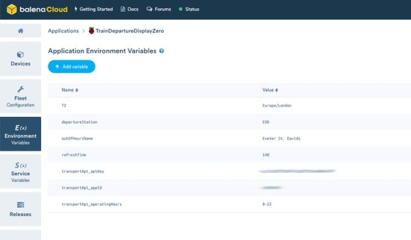
4.Add configuration variables
Instead of manually editing configuration files, you can set up your sign and change any variables at any time using the balenaCloud dashboard. We have great documentation on how to set environment variables if you need it, too.
The list of required environment variables for this project is on GitHub.
In order to obtain the key and application ID for the Transport API, you’ll need to sign up for an account. A basic account is free but limited to 1000 requests per day; but that’s plenty for this project!
At this point everything should be working and you should get your first glimpse of the working display!
Build a case
Now, to have the display just sitting on your desk is pretty cool, but I thought it would be even better to make it look like the real thing, or at least somewhere close.
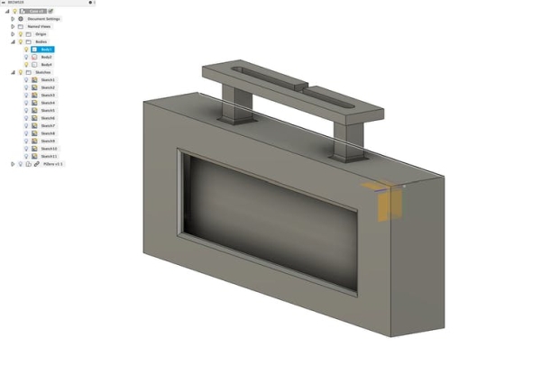
I designed a case to house both the display and Raspberry Pi Zero, ready to stick onto the bottom of my monitor. I wanted to make the case in such a way that it didn’t make everything too bulky, and so focussed on keeping everything tight together and not wasting too much space. I’m sure improvements could be made but I was happy with this as a first draft.
I use Autodesk Fusion 360 and a Creality Ender 3 (via Cura) printer. The models for this case are available on the balena Thingiverse page. It requires supports to print and I had the best results printing in the orientation below:
Source: Raspberry Pi Powered Live Train Station Desktop Sign