
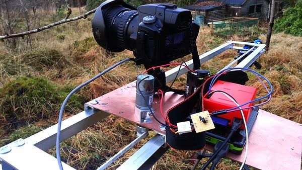
Here's my instructable for a home build timelapse dolly. The pro rigs for this are pretty pricey, so I made my own 🙂
Please vote if you like this project!
Step 1: Software
The heart of this machine is a Raspberry PI, a low cost small footprint computer. It runs linux so it's easy to write and deploy code on it. It also has a GPIO (General Purpose Input/Output) connector which we can control.
The code is pretty basic and written in python
I use the Raspian distro on my Raspberry Pi.
First, I installed Python, WiringPI and WiringPI-Python.
Next, I export the pins I will be using. I need two pins as outputs, so in a shell I type:
gpio export 18 out
gpio export 23 out
Now I can play around with pin 18 and 23.
Next, I write a python script to allow me to input exposure time, interval and number of shots. Here it is:
import wiringpi #get wiringpi-python
from time import sleep
io = wiringpi.GPIO(wiringpi.GPIO.WPI_MODE_SYS)
triggerpin = 18 #set my pins
motorpin = 23
io.pinMode(triggerpin,io.OUTPUT)
io.pinMode(motorpin,io.OUTPUT)
wiringpi.pinMode(triggerpin,1)
wiringpi.pinMode(motorpin,1)
exposure = input(‘exposure time: ‘) # pick exposure, interval and number of shots
interval = input(‘interval: ‘)
shots = input(‘number of shots: ‘)
motor = 72.8/shots
print ‘begin'
while shots != 0: # loop through actions until complete
io.digitalWrite(triggerpin,io.HIGH)
sleep(exposure)
io.digitalWrite(triggerpin,io.LOW)
sleep(0.5)
io.digitalWrite(motorpin,io.HIGH)
sleep(motor)
io.digitalWrite(motorpin,io.LOW)
sleep(interval)
shots = shots-1
print shots
You may notice the motor time is 72.8 / number of shots – this means I can select a number of shots and the Pi works out the motor times needed to run the length of the track.
I save this to a file named ‘timelapse.py'.
To make this easier to run in the field, I create a bash script to export the pins then run the python script:
#! /bin/bash
gpio export 18 out
gpio export 23 out
python timelapse.py
And save this as t.sh. I made it executable, so I simply need to type ./t.sh in a shell to get things up and running.
Step 2: Communicate with the Pi
I have an Android phone, so i can use the app ‘Connectbot' to connect to the Raspberry Pi via wifi and send commands.
I set up an ad-hoc wifi network to connect the phone.
This was straight forward enough – I edited /etc/network/interfaces and added the following:
iface wlan0 inet static
address 192.168.2.1
netmask 255.255.255.0
wireless-mode ad-hoc
wireless-channel 5
wireless-essid pi
auto wlan0
I also installed Screen on the Pi – this allows a session to run after SSH is disconnected so I can walk away from the rig whilst it still runs the last command I gave it.
Step 3: Electronics
There are two circuits in this project, the camera trigger and motor control.
Camera trigger
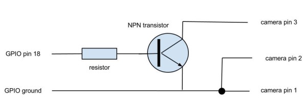
I use a Sony DSLR which has a port to connect a remote trigger. This has three pins – ground, autofocus and trigger.
The first step was to work out which pin was which. Using an old computer connector from a cd drive plugged into the port I was able to determine the first two pins were ground and autofocus. My camera needs the autofocus connection on before it will allow the trigger input to fire the shutter (regardless of whether I’m using autofocus or not).
So, I wire pin 1 and 2 together, allowing the camera to trigger by connecting the third pin to the joined 1 and 2. Result!
To trigger this from the Raspberry Pi I use the GPIO pins to control an NPN transistor, acting as a switch.
I used some transistors I had lying around, but 2n2222a NPN transistors should be a good choice for this.
470r resistors should be fine for these circuits too.
The top image is the camera circuit.
The resistor is in place to limit the current between the Pi and the transistor.
Motor control
Again, a switch is needed here, so the above circuit is repeated for the motor. However I’ve added a diode to protect the Pi from current generated by the motor when the power is cut but the motor still turns a little.
Step 4: Hardware
Motor
I worked out I’d need about 20 N*cm torque to drag my camera about – the motor came from Ebay, and runs on 4 AA batteries.
Rails
I wanted this to be light and strong. I sourced 1 metre long aluminium U-tubes from my local DIY store. The edge pieces are aluminium trim.
Platform
An aluminium sheet did the job here, allowing me to mount the motor securely. More of the aluminium U tubes made up the connection to the rails. I didn’t use any wheels as I wanted the platform to stop quickly after each movement.
Camera mount
A cheap one from my local camera shop did the job, it’s a basic ball mount for a tripod. I'll probably upgrade this at some point.
Timing belt/pulley
Another ebay purchase, the timing belt was originally for a large printer of some kind, but perfect for my needs. This is held in place with more sections of the U tube acting as a locking mechanism.
For more detail: Raspberry Pi powered time lapse dolly (RasPiLapse)