
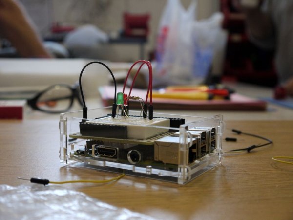
This is a basic prototyping kit for the Raspberry Pi. It will allow you to quickly and easily prototype your hardware ideas without the needing to buy new kit each time. It is also compact, portable, and a lot more durable than most prototyping kits. You can either build simple circuits on the top of the Raspberry Pi, or bridge to external board for larger builds.
Step 1: You Will Need
To build this you will need…
- A Raspary Pi 2 Model B
- An Adafruit Perma-Proto HAT for Pi Mini Kit
- Two 0.1″ (2.54mm) female pin header strips
- A SYB-170 breadboard
- An open top Raspberry Pi Case
- A double-sided sticky pad
- A short length of wire
You will also do well to get a breadboarding wire bundle plus some components to get experimenting and learning with. Some very basic projects to get started with are on Gordon Henderson's Wiring Pi web site and in the free MagPi magazine.
The basic tools you will need are…
- A soldering iron
- Wire cutters/strippers
- A small lump of Blue-tack
- A needle file
- A sharp craft knife

Step 2: Assembling the case
Using a case is optional but it will give an extra layer of physical protection and remove the chance of a metal object shorting out components on the Raspberry Pi.
Many case designs can be assembled without the top, but if you have access to a laser cutter, or want to send off to have a purpose designed case then you can download the custom Raspberry Pi case designed for this.
Once you have the parts simply hold the bottom in to the side with the holes, slide the Raspberry Pi in, and slide in the other side. Once this is done hook an end on the hooks at the top of the box and push it down so the hooks at the bottom clip it on, and repeat for the other end. To disassemble again push the end parts up and unhook from the top.
Step 3: Soldering the Pi HAT – Female Header Socket
First we want to attach the main female header socket that is used to attach it to the Raspberry Pi. This need to be held flat and to do this we are going to use a little trick with some blue (or in this case white) tack. Simply put the connector flat on the bench with the board resting on it. Now push the tack in the other side so it stays level when you let go.
Then we solder it on. If you have not done any soldering before then can I recommend following one of the many tutorials online. When you are ready to go simply tin the soldering iron, place it so it touches a pin and the Pi HAT at the same time, apply a little more solder between the pin and the Pi HAT, count slowly to two, then remove the soldering iron slowly. Repeat for the other 39 pins.
After you have done them all you can go back and apply the heat for a few more seconds to any that look a little messy and the will neaten themselves up.
Step 4: Soldering the Pi HAT – Female Pin Header
Now we need to add the female pin header strips. We will start with the main strip to access the GPIO pins.
The strips will be longer than we need to first we will cut one down. To do this put one in the Pi HAT so it overshoots one end and hold it so your thumb acts as a marker. Then cut through the hold after your thumb and file it down to make it a little neater. You can use the offcuts for the shorter strips.
Not we can use the blue / white tack trick again to solder this on to the top side from the bottom side. Then repeat for the other strips pictured.
You may notice I have added a lot more 3.3V pins than I will ever need but I had spare pins and the more I have the more convenient they are to reach. Also for neatness you can have a full length of 3.3V, GND, and 5V all together at the top that if desired, but this increases the chance of you inserting a wire in to the wrong hole. Feel free to change the layout if you prefer another layout.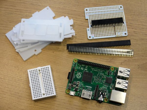
Step 5: Soldering the Pi HAT – Adding the Jumper Wires
We now need to add a couple of wires to connect the vertical headers to 5V and GND. First strip and tin a short length of wire. Also heat and add some solder to the 5V hole nearest the vertical header pins. Place the wire on top of this soldered hole, place the soldering iron on top, wait until the solder melts and fuses together, then slowly remove the soldering iron. Repeat with the same wire and the bottom of the end vertical strip. Then cut off the excess wire.
The other set of vertical headers is only one pin away so you can repeat this process, or add a quantity of solder to the two holes and draw it across with the soldering iron as I have in the end photograph.
For more detail: Raspberry Pi Prototyping Kit