
NSC-01
For Team Near Space Circus‘ participation in the Global Space Balloon Challenge with NSC-01, we wanted to make sure that once powered up, and enclosed, we would still have control of the computer cluster and the timeline of events, as to what would happen when. As we devised a network with 7 nodes (see part 1 and also part 2 of the computer network in near space) with a master controller and many slave nodes, we needed a way for the system to wait on a signal from us.
A plain old switch would do the trick of course. But what if the balloon took off and we forgot to flip the switch? Or somebody tripped and let the balloon go?
Then the master controller would have stayed in standby mode, sending keep alive frames to the other nodes and we would have had no images, no video, no gps data etc. Not good.

Tethered switch
If you've ever spent any time on a threadmill, no doubt you've encountered a tethered switch. Usually it's a magnetic plug, with a string, terminated by a clip. You clip it to yourself, so if you ever fall down/off the threadmill, you end up yanking the plug off the machine, and it stops right away.
Since the Raspberry Pi has many GPIO pins, all we needed to do was create a simple circuit between two of them that, once interrupted, would signal that it was time for the master controller to go to work.
| We will need two GPIO pins, how about GPIO17 and 27? |
Why two GPIOS? We could have connected a GPIO to 3V3 and GND through resistors (to protect/limit current), to ensure LOW and HIGH modes. But, trying to keep things as simple as possible from a hardware perspective (software doesn't weigh anything, hardware does), using two GPIOs made a lot of sense. Set one GPIO as input, one as output, raise the output HIGH, the input now sees a value of 1. Open the circuit (by pulling the wire out), and the input no longer sees HIGH, it now reads 0.
A string attached on one end to the wire sticking out of the side of the payload and on the other end to a carabiner clip is really all that was needed. 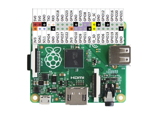
Deadman's switch code
We've already covered the serial port, sh and docopt in part 2 of the computer network in near space. If you are wondering about these things (and lines 98 to 101 in the code below) I urge you to go and read that article first. I've left here the core of what is needed for implementing the software side of the deadman's switch. We first need the GPIO module. On line 9, we import it as gpio (because uppercase is usually reserved for constants). Then on line 102 we set up the gpio module to operate in BOARD mode. That means physical board pin numbers. In the field, you can always count pins, but you might not have a GPIO map handy… But if you prefer Broadcom nomenclature there is a mode for that too.
For more detail: Raspberry Pi Python Adventures