
The GPIO: General Purpose Input/Output lets you interface your Raspberry Pi with the outside world, making it a powerful interactive device for just $40-$50.
This Instructable will show you how to install the GPIO package on your Raspberry Pi and how to wire up a simple push button circuit with an LED.

I use the command-line and Python for this, no web browser or GUI.
Before you do this Instructable, make sure you have your Raspberry Pi ready for action. My Ultimate Raspberry Pi Configuration Guide covers how to do this in detail.
You will want to have an internet connection to download the packages and probably use ssh.
Step 1: Gather your components
Components
* Raspberry Pi
* Cobbler breakout board with cable — you can order this from Adafruit for $8.
* Breadboard
* Wires — breadboard or otherwise
* standard LED
* 270 Ohm resistor
* 1K resistor
* 10K resistor
* Push button
* USB power for RPI (not pictured)
* Monitor + keyboard (not pictured)
Tools
* wire-stripper
* small diagonal snips
* multimeter for checking continuity
Step 2: Assemble your circuit
We will have a simple push button that will turn an LED on when the button is pressed and off when it is released. I know, it's not super-exciting, but think of this as a building block for digital input and output.
Here is the schematic and breadboard diagram.
The LED is straightforward: 270 Ohm resistor is needed to light up the LED from a 3.3V input.
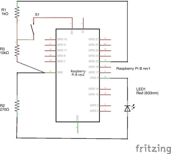
The concept is simple: the LED is an output of pin 4 and the button is an input of pin 22. The button circuit has a pull-down resistor. Pin 22 will be pulled down to zero through the 10K resistor when the button is inactive. When it gets pressed, the 3.3V power from the Raspberry Pi goes into the pin 22 input, bypassing the 10K resistor.
Without the 10K resistor, you'll have a floating input and will get erratic behavior in your code. The 1K resistor protects the Raspberry Pi from too much current.
Step 3: Putting it on the breadboard
After doing the wiring diagram in Fritzing, I laid out the components on a real breadboard. Strip the wires and use the diagonal snips for a clean-looking breadboard.
This is what it looks like with the Cobbler breakout board before I attach the ribbon cable to the Pi.
Even with a simple circuit like this, double-check your components to make sure you're not shorting your circuit or anything else like that.
Step 4: Connect to the Pi
Use the breakout cable and connect the cobbler to your Raspberry Pi.
You will want to be connected to the internet to download the latest packages via Wifi or an Ethernet cable.
Power up your Raspberry Pi.
For more detail: Raspberry Pi: Python scripting the GPIO