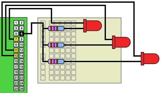
This video explains how to connect LEDs to a Raspberry Pi's general purpose input-output (GPIO) pins, and how to write Python code to turn them on and off.
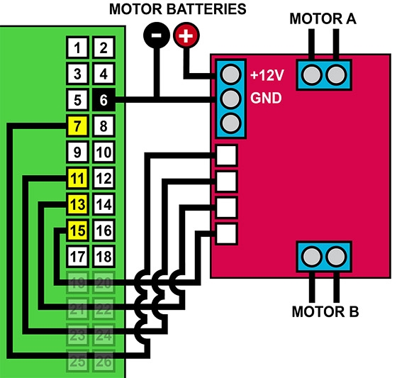
This video shows how to construct a Pololu Zumo robot chassis, how interface it to a Raspberry Pi using an L298N H-bridge motor controller, and how to use Python code to bring the robot to life!

The micro metal gear motors used in the video are available from Pimoroni here, or from Pololu here.
Pololu Zumo chassis kit is available from Pimoroni here, or from Pololu here.
Male-to-male and male-to-female jumper leads are available from Pimoroni here, or from Pololu here.
For the “L298N H-Bridge Motor Controller”, search for that term on Amazon or eBay. As at July 2014, one option on Amazon.com is here, and on Amazon.co.uk here.

In the video, and in the above diagram, I have not connected power from the Raspberry Pi to the 5V connection on the L298N board. This is because the L298N board I used has a “5V enable” function that allows the electronics on the board to be powered from the battery pack via an on-board voltage regulator. This function is controlled by a jumper on the board behind the three-pin power connection block. If, however, your L298N board does not have this function — or if your board has this function and you remove the jumper! — you will need to connect the 5V line from the Raspberry Pi (ie GPIO pin 2) to the 5V terminal on your L298N. But do not do both! If in doubt as to the function of your L298N board, start without GPIO pin 2 connected to the 5V terminal — and if nothing works, try again with this connection made. 🙂
For more detail: Raspberry Pi Robotics #1 GPIO Control

