
I found an old Western Electric rotary phone in my attic. It's really an amazing piece of hardware. It seems to work fine several decades after its construction despite whatever abuse it took before ending up in my attic. However, I don't currently need a rotary phone.
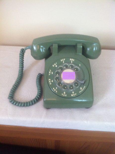
So I decided to put a Raspberry Pi inside it. I decided to make it an MP3 player that's simple and robust for my daughter, but I guess it can actually be a general-purpose (if inconvenient) computer.
The pictures show the finished product. My goal was to leave the phone as intact as possible (ars est celare artem), so the main sign anything has changed is that the port on the back is now micro USB rather than a modular phone jack. I also added a switch to power down the Pi in the handle below the hook, but I wish I hadn't — the handle was really comfortable for carrying the phone and the switch gets in the way. So these instructions don't show that part. Since I wanted to add as little as possible, I put the speakers in the headset.
Step 1: Gather Hardware
Here are the things I used.
- rotary phone
- Raspberry Pi I used a model B but it should be possible to modify the instructions for another model instead
- 8G Micro SD card w/ SD adapter
- USB Audio Adapter
- 4x 10k ohm resistors
- 5x motherboard standoffs
- 5x motherboard screws
- Jumper Wires
- Wire Connectors
- 2x micro speakers
- Stereo plug
- USB MicroB Female Plug
- USB MicroB Male Plug
- Polycarbonate Sheet
Step 2: Prepare phone
First you have to open the phone and remove the stuff that takes up all the space
Next, I cut a polycarbonate sheet to mount the Pi away from the metal base. I cut with a box cutter, scoring halfway through then cracking at the cut. Then I drilled holes by hand — I broke some pieces using an electric drill, but maybe I lack technique.
The first picture is the template I cut from. The second picture is the actual sheet I used. Obviously I made some mistakes getting the sheet to look like the template. In particular, I accidentally broke the tab in the upper right, which I still think would be better to have but oh well. Also I put several holes in the wrong places. The measurements on the template are close but I actually drilled by putting the sheet in place and marking.
The third picture shows the sheet with screws attached. These will eventually attach the Pi to the sheet.
The fourth picture shows the sheet mounted to the base of the phone, and the fifth shows the Pi positioned on the sheet.
Step 3: Wiring phone devices
To figure out how to use the phone devices as input to the Pi, I used this schematic.
Basically, the hook, the rotary, and the dial can be viewed as independent switches. The hook switch is open when the receiver is on the hook then closes when the receiver is lifted. The dial switch is open when the rotary is in its default position and closes when the rotary is moved away from the default (opening again when it gets back). The rotary switch rests in the closed position, then opens and closes as many times as the number that was dialed.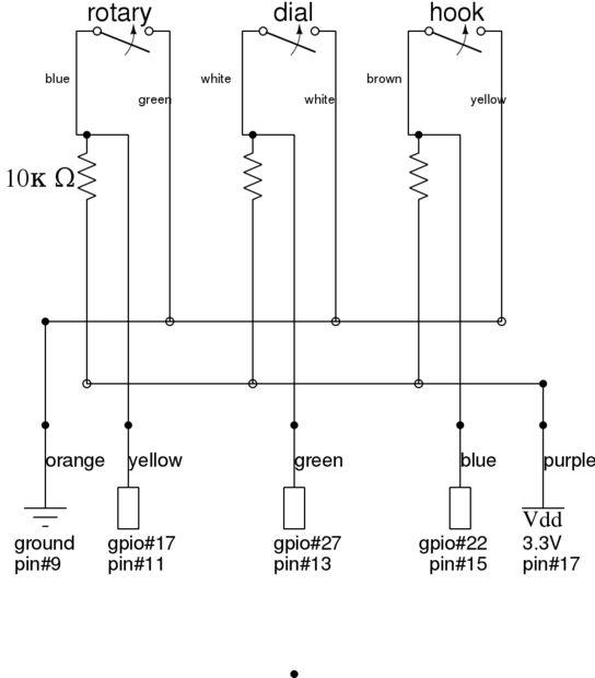
I wired each of these switches to a GPIO pin using a jumper cable. For each switch, I included a 10k ohm resistor as shown in the wiring diagram. In the diagram, the top color labels describe the colors of the wires in the phone. The bottom color labels are just colors I used but do match what's pictured in the second picture.
To make it easy to connect and disconnect the wiring, I made my own “rainbow cable” by gluing together the jumper terminators. I chose a row of GPIO pins that were all in a line. Specifically I connected to pins 9,11,13,15 and 17 which include a ground (pin 9) and a 3.3V (pin 17) and between them three GPIO pins. I wired the rotary to pin 11, the dial to pin 13 and the hook to pin 15, as shown in the diagram.
For more detail: Raspberry Pi in Rotary Phone