
I started exploring how to get a LCD display operational with a Raspberry Pi (RPi). I checked out two hardware configurations: the bare bone LCD 16×2 display driven by the HD44780 chip set, which takes 6 wires to operate, and another configuration that uses a Adafruit shield that requires only 2 wires. It quickly became clear to me that I knew very little about how the LCD display works (maybe not an important topic for me) and I didn’t fully understands the RPi’s serial communications capabilities (something I must fully understand). Adafruit does give some nice tutorial that provide instructions on how to get both configurations work on the RPi, but I don’t like blindly follow tutorials without having a deeper understanding of my options and the underlining hardware. So what are the serial communication options supported by the Raspberry Pi, under what situations would you use them, and how do you use them?
The Raspberry Pi Board
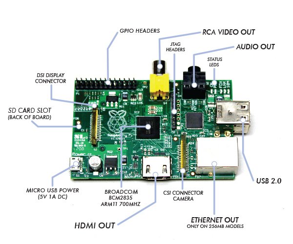
As our first step, lets take a quick scan of the interfaces we have on RPi for moving data in and out. The picture below labels the most prominent components on the RPi board.
Of course, the “lead actor” on the RPi board is the Broadcom BCM2835, System on a Chip (SoC). Broadcom bills this chip as a “multimedia applications processor for advanced mobile and embedded applications that require the highest levels of multimedia performance”. Maybe more importantly for the DIY/Hacker community is that all the firmware running on the chip is now open source.
There is another big chip, that being the SMSC LAN9512/LAN9512i USB Hub & Ethernet Controller. This is the major work horse in getting data in/out of the RPi for USB peripheral devices and IP networking.
Now note that most of the board’s other large components are for data I/O. Specifically, the HDMI, RCA Video, and Audio Out (3.5mm jack) are output only (at least for general purpose data communication perspective), and therefore, not part of our discussion. On the other hand, the USB and Ethernet ports, are powerful and widely supported serial communication devices, but I will only lightly touch the USB. I want to focus on serial communication with simple/bare-bone devices, like an LCD 16×2 display, which generally are not interface via something as sophisticated at USB or Ethernet. But the USB can be used to some for some types of device interfacing, so I will cover that as a final topic.
There are three other board components that concern themselves with data communications but will not be covered in this post:
- JTAG Header: The JTAG Header is used as a debug port. Embedded systems developer relies on debuggers communicating with chips via the JTAG to perform operations like single stepping and break-pointing. In time, I suspect people will find ways to exploit these pins for both good & evil, but for now, this is for the RPi hardware development community to use.
- CSI Camera Connector: The Camera Serial Interface (CSI) specification is a standard interface between a camera and a host processor for mobile device applications. This will be where you’ll connect cameras and video devices to the RPi.
- DSI Display Connector: The Display Serial Interface (DSI) is a specification aimed at reducing the cost of display sub-systems in a mobile device. This is commonly targeted at LCD and similar display technologies. RPi may be able to interface to some of these. Some graphical LCD/OLED displays might be attached to it. DSI would seem like a good candidate for implementing my LCD display but there is a problem. It appears the DSI isn’t supported at this time.
This leaves one remaining board input/output component standing, that be the General Purpose Input/Output (GPIO). On some electronics boards, GPIO pins have no special purpose defined, and some pins go unused by default. The RPi developer has identified a handful of digital control lines and provided services on them for you to use. By having these available can save you the hassle of having to arrange additional circuitry to provide them or implement functionality in software.
Raspberry Pi’s GPIO as a Data Bus
The first thing to get your head around, is how is data moved around the RPi, or in any general purpose computer. In the most general sense in electronics, a bus or data bus is used to move data words of any type from one place to another. Computing is based on data words made up of collections of data bits. These “words” can contain as few as four data bits and often much larger.
The task of a bus designer is to devise circuitry that passes these data words from one circuit to another. These words can be communicated serially (i.e. serial communications) or in parallel.
- Serial Bus: The least expensive method in terms of wire cost is to send the bits one at a time over a single pair of wires. This is called serial data transmission. Data words start as sets of bits that exist in parallel. In order to ship these words on a serial basis they must be converted to a serial stream of bits at the transmit end and then reconverted to a parallel word at the receive end. The common name for the circuitry that does this conversion is a SerDes circuit which stands for serializer/deserializer. Integrated circuits are more expensive when they have more pins. To reduce the number of pins in a package, many ICs use a serial bus to transfer data when speed is not important. Some examples of such low-cost serial buses include Serial Peripheral Interface (SPI), Inter-Integrated Circuit (I²C), UNI/O, and 1-Wire.
- Parallel Bus: At some point, it is more cost effective to add a wire for each bit in the word and send it in parallel on a data bus. Parallel buses have a limited data rate and distance at which they can be reliably run (more so than a serial bus). Some widely used parallel bus standards are Parallel Bus Interface (PBI), Peripheral Component Interface (PCI), Small Computer Systems Interface (SCSI), the VMEbus used in instrumentation, the Rambus interface used in memories, and others.
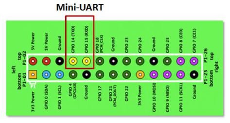
As the name implies, GPIO pins can be configured through software to provide some specific function or purpose within the hardware device design. The GPIO pins connect directly into the core of the processor, and the Raspberry Pi developers implemented several alternate functions for the GPIO pins. Several are desirable because of the multiple standards and types of devices you may wish to interface. On boot-up, the RPi board GPIO is in alternate function state “ALT0″ and will support I2C, SPI, and UART.
It can be confusing to call the RPi’s whole 26 pin array GPIO and also some specific pins GPIO. In reality, all the GPIO pins can be reconfigured to provide alternate functions.
While PCM isn’t a topic for this posting, in the figure above, you’ll also see references to PCM on pins 18 & 21. PCM stands for Pulse-code modulation and is s a method used to digitally represent analog signals. It is often used to control light intensity or motors. RPi’s native PCM capabilities are not well documented but it appears that people have has some success. Generally, to do anything useful, you need multiple PCM channels so people have resorted to adding hardware or software to get the desired functionality from the RPi. My guess is these RPi pins don’t have much of a future.
I2C, SPI, UART … Say what?
Much has been lightly covered so far, including terms like I2C, SPI, and UART. So what is the significance? Well, I2C, SPI, and UART are the heart of our quest to understand RPi’s serial communications capability. Via their exposure on the GPIO pins, these capabilities are what can be used to integrate things like LCD displays to the RPi. Now lets dive deeper into each one of them.
Universal Asynchronous Receiver/Transmitter (UART)
The Universal Asynchronous Receiver/Transmitter (UART) takes bytes of data and transmits the individual bits in a sequential fashion. The device changes processor’s parallel information to serial data which can be sent on a communication line. A second UART (maybe on another processor) can be used to receive the serial information. The UART performs all the tasks, timing, parity checking, etc. needed for the communication. The only extra devices attached are line driver chips capable of transforming the TTL level signals (0/5 volts) to line voltages (on RS-232 line this could be as +/- 25 volts) and vice versa.
Each UART contains a shift register, which is the fundamental method of conversion between serial and parallel forms. Serial transmission of digital information (bits) through a single wire or other medium is much more cost effective than parallel transmission through multiple wires. The UARTs transmit/receive one bit at a time at a specified data rate (i.e. 9600bps, 115,200bps, etc.). This method of serial communication is sometimes referred to as TTL serial communications.
Asynchronous transmission allows data to be transmitted without the sender having to send a clock signal to the receiver. Instead, the sender and receiver must agree on timing parameters in advance and special bits are added to each word which are used to synchronize the sending and receiving units. When a word is given to the UART for Asynchronous transmissions, a bit called the “Start Bit” is added to the beginning of each word that is to be transmitted. The Start Bit is used to alert the receiver that a word of data is about to be sent, and to force the clock in the receiver into synchronization with the clock in the transmitter.
For a further description of synchronous and asynchronous line communications, check out this tutorial.
Raspberry Pi’s Mini-UART
Warning: Misleading information ahead – See Warren Gay’s comments.
The Raspberry Pi actually has two UARTs. One UART is part of the internal ARM architecture of the Broadcom BCM2835 chip, in the core of the Raspberry Pi and not accessible externally. The other UART is sometimes called the RPi’s “Serial Port” (even thou the USB supports serial communications, and therefore a serial port). The serial port being reference here is serviced by a UART, sometime refereed to as the “Mini-UART” since it doesn’t appear to be very rich in functionality. It is basically be used as a console port for access to the Raspberry Pi. The serial console is a convenient way to interact with the Raspberry Pi for debugging or your network is down and it is the destination of console messages (including boot-up messages). From the Raspberry Pi pinout and the eLinux wiki, I can see that the serial port (aka Mini-UART) on the Pi is on GPIO Pin 14 (TX) and GPIO Pin 15 (RX):
ince the GPIO pins give access to the Mini UART, you can establish a serial console, which can be used to log in to the Pi, and many other things. However, normal console device communicate with -12V (logical “1″) and +12V (logical “0″) RS-232, which may just fry something in the 3.3V Pi. Even “TTL level” serial at 5V runs the same risk. See this tutorial for one example on how to build 3.3V to RS-232 levels converter with a MAX3232CPE and a few passive components.
You can reconfigure the RPi so that the Mini UART isn’t acting as a serial console and use it for outer purposes (e.g. communicate with an attached Arduino or Xbee). Using the Raspberry Pi’s serial port requires some Linux reconfiguration and the abandonment of the serial console, and potentially some level conversion, but it could be useful. The Mini-UART pins to provide access to Linux’s /dev/ttyAMA0 serial port. To be able to use the serial port to connect and talk to other devices, the serial port console login needs to be disabled and the post “Raspberry Pi and the Serial Port” shows you how.
Again, keep in mind that RX and TX lines are available on the GPIOs but operate at 3.3 volts. You’ll need a board or cable to level convert 3.3 volt UART signals to connect with other devices (e.g. RS-232, USB).
For more detail: Raspberry Pi Serial Communication: What, Why, and a Touch of How