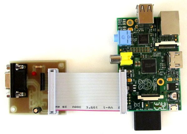
erial port to the Raspberry PI and breaks out some of the PI's pins for experimentation.
The interface board was designed to be simple and used for initial experimentation. It can be built on a single-sided PCB using home-made PCB fabrication methods.
KiCad source files are provided so that the design can be modified if needed.
The RS-232 serial port allows the Raspberry PI to be programmed by connecting it to a PC without the need to connect a keyboard and screen to the PI.
Circuit Diagram
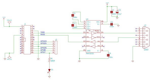
The circuit diagram for the Raspberry PI serial port breakout board is shown below.
As the circuit diagram shows, the design is very simple. The board contains one RS-232 level converter chip and breaks out 5 of the Raspberry PI's GPIO pins. An LED and series resistor is connected to one of the GPIO pins.
Board Construction and Assembly
Surface mount parts were used for the MAX3232 RS-232 chip and 100n capacitors as can be seen in the photo below. These parts can easily be changed to through-hole parts using the KiCad source files provided if desired.
A surface mount MAX3232 was chosen as they are generally cheaper and more easily available than the through-hole mounting equivalents.
Circuit Board Design and Construction
The board was designed and constructed using the methods described in the book Open Source Electronics on Linux. This book can be used to learn KiCad and the toner-transfer method of home PCB construction.
Soldering
The surface mount parts are not difficult to solder and should be soldered first. They are mounted on the copper side of the circuit board. The 100n capacitors have a 1206 footprint size so are big enough to handle easily.
The through-hole resistor, LED and capacitor should be soldered next, followed by the connectors.
For more detail: Raspberry PI Serial Port and Breakout Board


