
I have been working with the Raspberry Pi for a few months and have had a great time experimenting.I plan on documenting some of the things that I have been able to do and observations that I have made.
My latest project is to use the Pi to read temperature from multiple DS18B20 sensors and graph the results – my notes are here
I have also been working on a Temperature / Humidity grapher – notes re here:
http://www.trainelectronics.com/RaspberryPi/Graph_Humidity/
Easy Case
I made a protective Plexiglas case using materials that I found at my local (well stocked) hardware store.Two pieces of 1/4″ Plexiglas are held apart by 3/4″ spacers (stand offs). The Plexiglas is 4.5″ x 3″.
There are three nylon screws that go through tapped holes in the top piece of Plexiglas to put gentle pressure on three points on the board, holding it firmly in place. The screws are 6 x 32 and 1″ long. The screws that goes onto the yellow video out connector is way too long and will be cut down in length.
If you can't find nylon screws locally I purchased 8-32 x 1″ screws from MicroFasteners.com 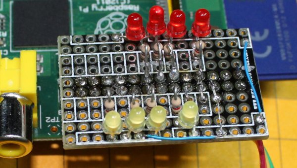
A small piece of 1/8″ thick gasket material (2″ x 1.75″) goes under the side of the board away from the SD car socket. This padding helps to level out the bottom and it keeps the board from moving. The gasket material was found in the plumbing department. Make sure you test it to make sure that it DOES NOT conduct electricity before using it! The material I found is rubber and works well. It is similar to this item from Sears.
A slot can be cut into the top piece of Plexiglas it access to the I/O pins is needed.
If you look carefully at the spacers in this photo you will note that the screws are not fully tightened but there is a small space between the stand off and the Plexiglas. A small washer will be added to fill this space.
UNDER CONSTRUCTION!!!
Using the Pi to Communicate with a Pic (or PICAXE) Microcontroller
The serial port on the Raspberry Pi can be used to send data strings (text and/or data) to other devices. The objective of this project is to get the Pi to send meaningful data to a Pic or PICAXE processor.
Testing the Serial Output
Start a terminal program on the PC. Set it to 115200 baud, N, 8, 1 – no flow control. Make sure that the correct com port is selected.
Connect the UART pins from the Pi to you computer's serial port using the MAX3232 described below.
To send a serial string from the Pi's command line type the following:
echo “hello” > /dev/ttyAMA0 and press ENTER – note that the last character is a zero not an “O”
To send with a carriage return and line feed:
echo -e “hello \r\n” > /dev/ttyAMA0 and press ENTER
Modification to Shell file to Send Serial
I modified the shell script that was shared here: http://www.instructables.com/id/Web-Control-of-Raspberry-Pi-GPIO/?ALLSTEPS so that it would output serial data via the UART that I could receive with a PIC or PICAXE so that the web input would control the microcontroller to do stuff!
The modified GPIOServer.sh file is here: RaspberryPi/GPIOServer-EchoWorking.sh.txt
Here are the changes I made:
- In each of the 8 IF THEN ELSE statements I added code to set 8 different single letter variables (a–>h) to either 1 (if true) of 0 (if false)
Note the line that says a=1 just above the ELSE statement and the line that says a=0 just above FI – this is repeated with b=1 and b=0, c=1 and c=0 and so on - At the end of the 8 IF THEN ELSE statements I added an ECHO statement to send a set of 0's and 1's representing the state of the 8 switches – the lines that I added are here:echo “xyz”$a$b$c$d$e$f$g$h
echo -e “xyz$a$b$c$d$e$f$g$h \r\n” > /dev/ttyAMA0The first line echo's the string of 1'a and 0's to the screen while the 2nd line sends the same thing to the serial port
The -e and \r\n adds a carriage return and line feed
- The results that are sent to the screen and serial port look like this:
xyz0011010101 or xyz10001000 depending on the setting of the bits on the web page
the “xyz” at the start allows the PIC or PICAXE to start importing data after that string is seen. - I also changed the baud rate from 115200 to 2400 as the PIC and PICAXE can't handle the higher speed. Notes on changing the baud rate are here: http://www.andremiller.net/content/raspberry-pi-and-arduino-via-gpio-uart
PICAXE 14M2 Program
This is the test program that successfully picks up data from the Pi and sends it back out to a terminal program
SYMBOL SerialIn =c.0 ‘pin 7
SYMBOL Delay = b6
SYMBOL cameras = b5
setfreq m16 ‘run the PICAXE at its highest speed (16MHz)
Startit:
serin c.0,n2400_16,(“xyz”),bit0,bit1,bit2,bit3,bit4,bit5,bit6,bit7 ‘ get 8 characters only after seeing “xyz”
cameras=b0 & %00001111 ‘cameras to use are the last 4 bits
delay = b0 & %11110000 ‘delay time is the first 4 bits
b1=b1+1 ‘just a counter to show it is working
delay=delay/16 ‘ move the delay bits four places to the right
serout 1,N2400_16,(#b1,” Cameras = “,#cameras,” Delay= “,#Delay,13,10) ‘send to terminal on PC for testing
goto Startit:
PICAXE 14M2 Program for Camera Controller
'01-13-2012 v 1.9 revised for latest board version
‘ d. bodnar
‘Video Switcher
‘w0 = b1 : b0
‘w1 = b3 : b2
‘w2 = b5 : b4
‘w3 = b7 : b6
‘w4 = b9 : b8
‘w5 = b11 : b10
‘w6 = b13 : b12 etc
#PICAXE 14M2
‘#TERMINAL 19200
setfreq m16 ‘run the PICAXE at its highest speed (16MHz)
SYMBOL SerialIn =c.0 ‘pin 7
SYMBOL Camera1 = 2
SYMBOL Camera2 = 3
SYMBOL Camera3 = 5
SYMBOL Camera4 = 4
SYMBOL Delay = w6
SYMBOL UseCamera4 = bit3
SYMBOL UseCamera3 = bit2
SYMBOL UseCamera2 = bit1
SYMBOL UseCamera1 = bit0
SYMBOL cameras = b5
pause 1000
serout 1,N2400_16,(“Video Switcher”,13,10)
serout 1,N2400_16,(“(c) d. bodnar v 2.0 Pi Serial 07-29-12”,13,10)
Start:
serin c.0,n2400_16,(“xyz”),bit0,bit1,bit2,bit3,bit4,bit5,bit6,bit7 ‘ get 8 characters only after seeing “xyz”
cameras=b0 & %00001111 ‘cameras to use are the last 4 bits
delay = b0 & %11110000 ‘delay time is the first 4 bits
b1=b1+1 ‘just a counter to show it is working
delay=delay/16 ‘ move the delay bits four places to the right
delay = 16-delay
serout 1,N2400_16,(#b1,” Cameras = “,#cameras,” Delay= “,#Delay,13,10) ‘send to terminal on PC for testing
‘READADC10 0, Delay
delay = delay * 1000*4
serout 1,N2400_16,(“Delay Time = “,#delay,13,10)
‘debug delay
IF UseCamera1=0 THEN
serout 1,N2400_16,(“one”,13,10)
LOW Camera2:LOW Camera3:LOW Camera4
HIGH Camera1
PAUSE Delay
ENDIF
IF UseCamera2=0 THEN
serout 1,N2400_16,(“two”,13,10)
LOW Camera1:LOW Camera3:LOW Camera4
HIGH Camera2
if usecamera3=1 and usecamera4=1 then
delay = delay -3000
PAUSE Delay ‘skip delay if last
else
pause delay
endif
ENDIF
IF UseCamera3=0 THEN
serout 1,N2400_16,(“three”,13,10)
LOW Camera1:LOW Camera2:LOW Camera4
HIGH Camera3
if usecamera4=1 then
delay = delay – 3000
PAUSE Delay
else
pause delay
endif
ENDIF
IF UseCamera4=0 THEN
serout 1,N2400_16,(“four”,13,10)
LOW Camera1:LOW Camera2:LOW Camera3
HIGH Camera4
delay = delay – 3000
PAUSE Delay
ENDIF
IF UseCamera1=1 AND UseCamera2=1 AND UseCamera3=1 AND UseCamera4=1 THEN
serout 1,N2400_16,(“NONE”,13,10)
LOW Camera1:LOW Camera2:LOW Camera3:LOW Camera4
ENDIF
GOTO Start:
UNDER CONSTRUCTION!!!
Using the Pi to Control a Web Cam System
I have been using a four camera web cam system for some years. You can view the live video here. The board that switches between cameras was originally designed to be operated by using four switches to select one or all of the cameras and a potentiometer to select the time that each camera would be active. The project was featured in Make Magazine, Issue 30 in the Spring of 2012. This article can be viewed here: http://www.trainelectronics.com/WebCam/Article.htm
The objective of this project is to use the Raspberry Pi, and its web interface, to select cameras and time delay. The project uses a number of routines and programs that have been written about using the Pi. My hat is off to all of those contributors who made this work possible!
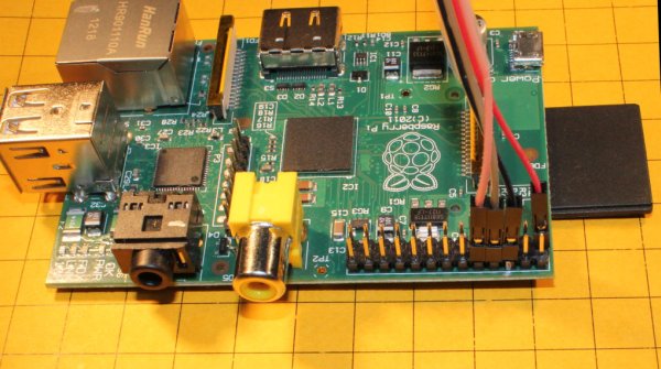
- Set up the Pi as shown here: http://www.raspberrypi.org/quick-start-guide
- Set up the Pi for web control as shown here: http://www.instructables.com/id/Web-Control-of-Raspberry-Pi-GPIO/?ALLSTEPS – this gives you the ability to use a web server on any computer to remotely control the 8 IO pins on the Pi's expansion header.
- Build a plug & test board to connect to the header The board that I used is from Sure Electronics
- – Each of the boards can be broken into four smaller boards like what I am using here.
The in-line header is also from Sure. It can easily be cut into two thirteen pin strips for our board.
LEDs and 1K resistors were added to each I/O pin. Note that the far left and far right sets of holes are connected to ground.
For more detail: Raspberry Pi – single board Linux computer