Use a Raspberry Pi to make your “dumb” car smarter!
Story
INSPIRATION
I love the idea of smart cars, but it's hard for me to justify purchasing a whole new car just to get a couple of bells and whistles. For the time being, I'm stuck with my “dumb” car, but that doesn't mean I can't try and make it smarter myself!
The term “Smart Car” can have dozens of different meanings depending on who you ask. So let's start with my definition of a smart cart:
- Touchscreen interafce
- Backup camera that let's you know if an object is too close
- Basic information about the car, such as fuel efficiency
- Maybe bluetooth connectivity?
I'm not sure which, if any, of those items I'll have any success with, but I guess we'll find out.
THE BACKUP CAMERA
The first obvious addition to our smart car wannabe is a backup camera. There are many kits out there that makes adding a backup camera pretty simple. But most of them require making modifications to the car itself, and since I'm just wanting to test a proof of concept, I don't really want to start unscrewing and drilling into my car.
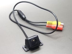
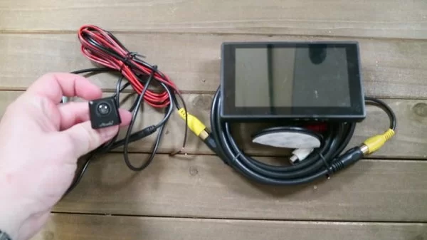
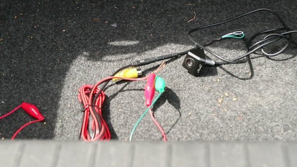
Regardless, I went ahead and ordered a cheap $13 backup camera and a USB powered LCD screen.
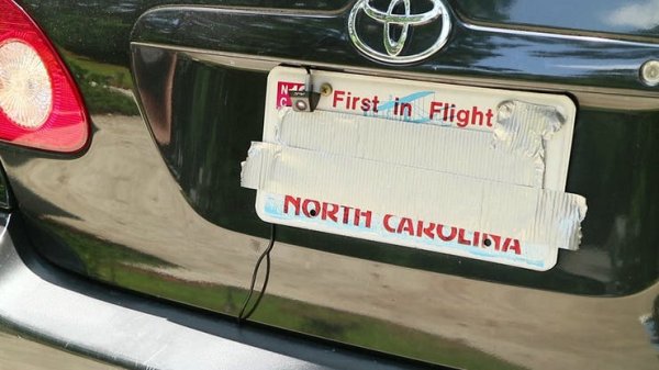
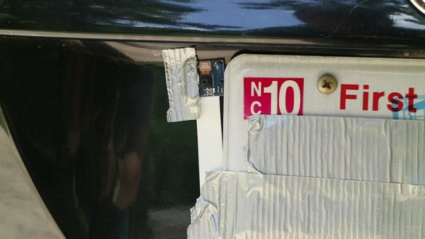
One caveat with cameras like these is that they require and external power source. Generally it's prescribed to wire them to one of the reverse lights of your car so that it's automatically powered on when the car is in reverse. Being that I don't want to modify my car at this time, I'm just going to wire it up to some batteries. And I'll mount it to the license plate using trusty old duct tape!
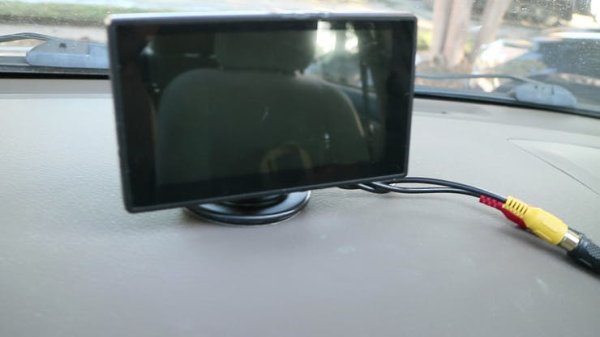
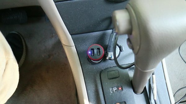
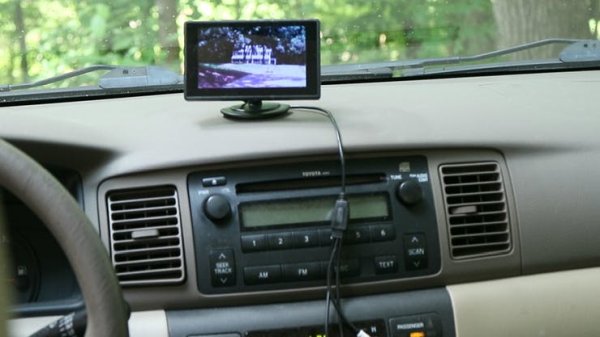
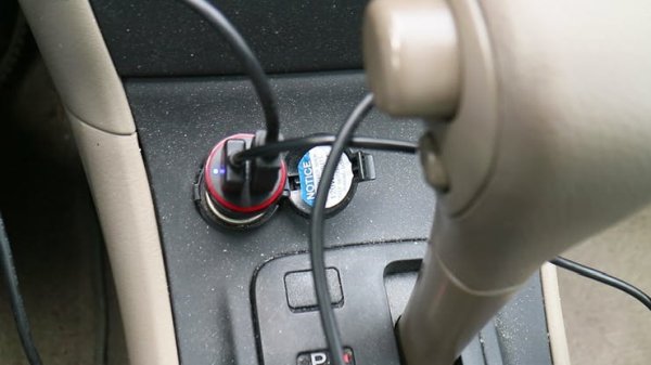
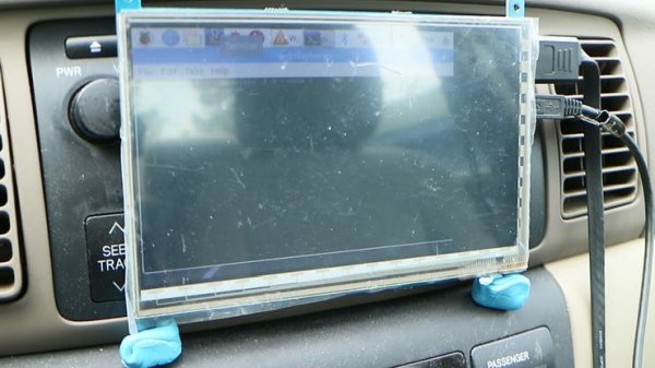
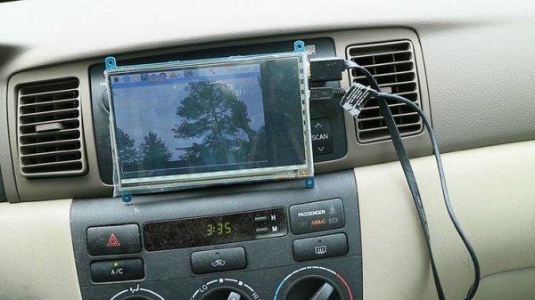
I ran an RCA cable from the camera to the dashboard and connected it to my 5′ LCD. This specific LCD can be powered through USB, so I plugged it in to a USB lighter adapter (most old cars have lighter adapters).
After starting the car, the screen immediately came on and I could see the image from the camera. Works as advertised! This would be a good solution for anyone just wanting to add a backup camera to their car, and don't want any bells and whistles with it. I think I can do better, however.
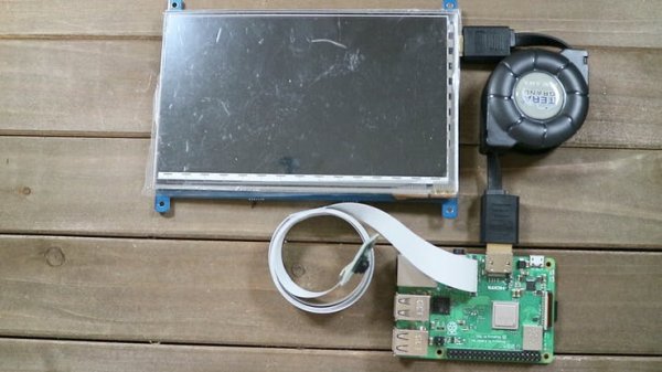
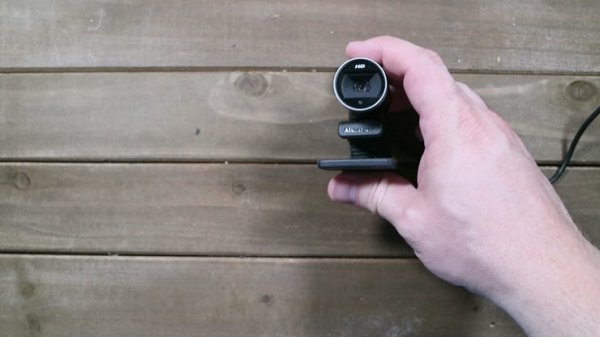
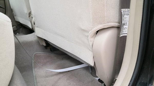
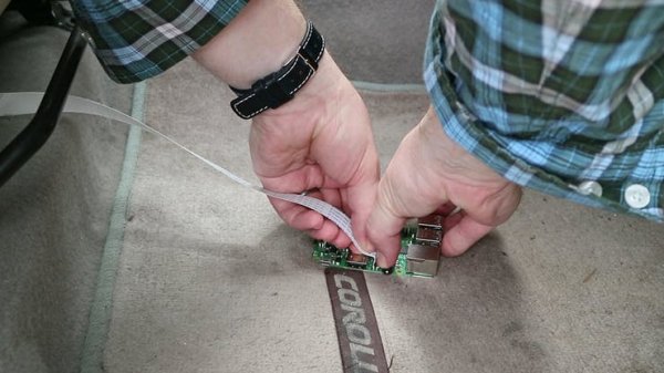
Enter the Raspberry Pi. The Pi is the perfect platform for a smart car, because it's basically a mini computer with tons of inputs and outputs. When connecting a camera to the Pi, you can use practically any generic USB webcam, or you can go with Pi Camera. Neither camera requires a separate power source. But just make sure you have plenty of cable to go to the back of the car.
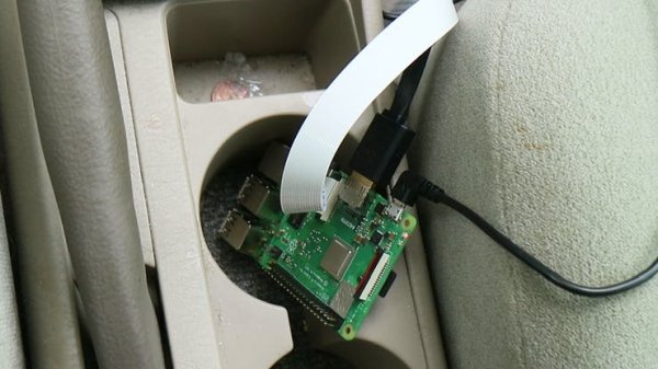
Turning on the car, both the Pi and the screen powered up. One obvious downside is the boot time required for the Pi to boot up…something I'll have to consider later. To view the Pi cam, I opened up the terminal and ran a simple script (a script that can be set to auto-boot in the future)
raspivid –t 0
or
raspivid –t 0 —mode 7
After hitting enter, a feed of the video camera popped up! The nice thing about video on the Pi is that you can analyze it, and maybe even set up an alert system if an object gets too close! So let's work on that next!
OBJECT DETECTION
METHOD 1
When it comes to commercial backup cameras, there are generally two versions that I've seen. The first uses a static overlay with color ranges so that you can visually determine how close an object is. The second method uses a camera in conjunction with some type of sensor that can sense how close an object is to the car and then alerts you when something is too close.
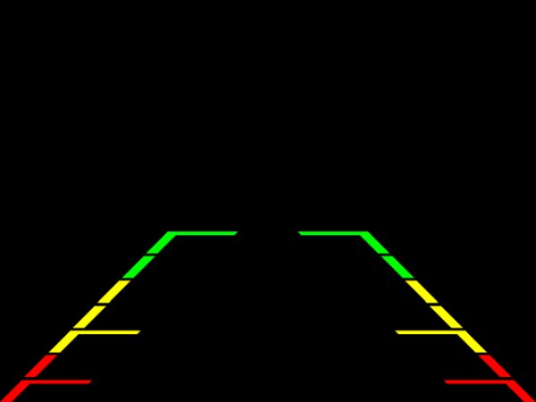
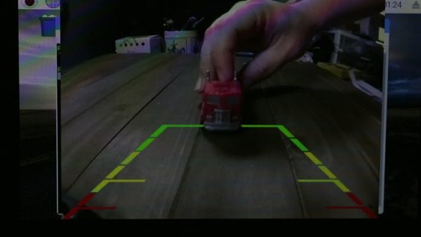
Since the first method seems easier, let's try that one first. Essentially, it's just an image overplayed on top of a video stream, so let's see if recreating it is as easy as it sounds. The first thing we'll need is a transparent image overlay. Here's the one I used (also found on my github repository):
The image above is exactly 640×480, which just so happens to be the same resolution my camera will be streaming at. This was done intentionally, but feel free to change the image dimensions if you are streaming at a different resolution.
Next we'll create a python script that utilizes the PIL python image editor and the PiCamera (if you are not using a Pi Camera, then adjust the code for your video input). I just named the file image_overlay.py
import picamera
from PIL import Image
from time import sleep
#Start a loop with the Pi camera
with picamera.PiCamera() as camera:
camera.resolution = (640, 480)
camera.framerate = 24
camera.start_preview()
img = Image.open(‘bg_overlay.png')
img_overlay = camera.add_overlay(img.tobytes(), size=img.size)
img_overlay.alpha = 128
img_overlay.layer = 3
while True:
sleep(1)
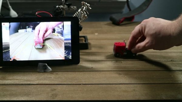
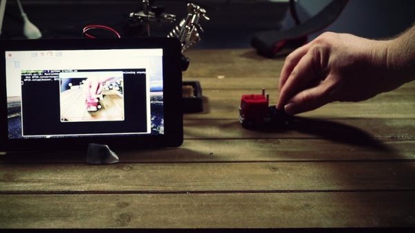
Saving it and testing it out by running “python image_overlay.py”, I tested it out on a small scale using a toy car to see how it worked. It worked like a charm, and there was practically no lag!
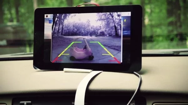
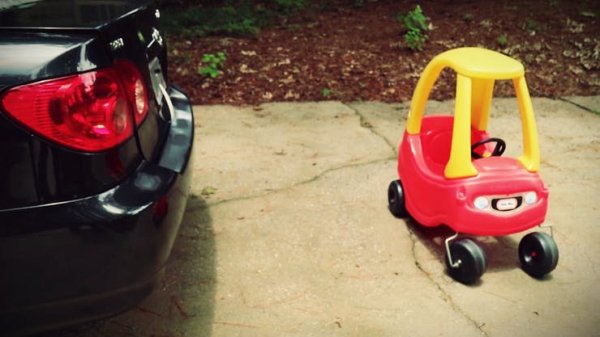
Loading it in the car and running the program, the results were equally as charming! One very important thing to note, however, is that you should take particular care in calibrating your camera to make sure the base of the video view is as close to your car bumper as you can get it. As you can tell in the pictures below, the camera was facing too high, so the test object was actually much further away than what the camera told me.
The Method 1 test was very successful, but it was also very basic. It would be nice to have a system that can detect how far the object is from the car and notify you if it gets too close. As I mentioned before, most cars that have that feature use external sensors that can detect objects. I'm not really keen on adding any other external devices to my car, so I'm going to see if I can detect objects using computer vision.
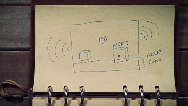
I can use OpenCV with python as my computer vision API. This will allow me to analyze what's in the image and to set parameters for whatever is found. So the idea would be to take the video footage and set a boundary at the bottom (close to the car bumper) for the “alarm zone”. Then I'll have it detect whatever large objects are in the footage. If the bottom most area of the objects enters the “alarm zone”, then it should send an alert message.
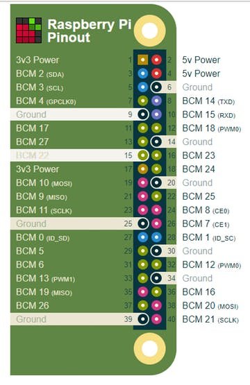
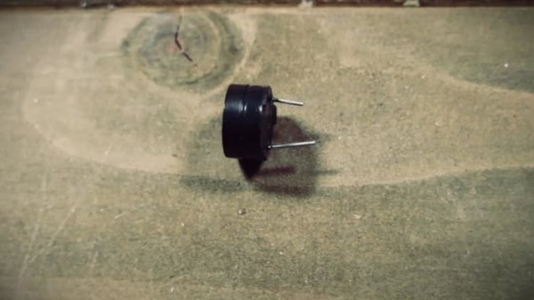
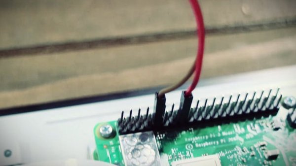
To serve as the alret sound, I'm going to wire a piezo buzzer to the Raspberry Pi by connecting the positive leg to Pin 22 and the negative leg to a ground pin.
Before starting on the code, we have to install OpenCV on the Pi first. Luckily the Pi can do this through the Python “pip” command
pip3 install opencv-python
Once OpenCV is installed, we can create a new Python file and start on the code. For the fully documented code, you can visit my github repository. I just named my file car_detector.py
import time
import cv2
import numpy as np
from picamera.array import PiRGBArray
from picamera import PiCamera
import RPi.GPIO as GPIO
buzzer = 22
GPIO.setmode(GPIO.BCM)
GPIO.setup(buzzer, GPIO.OUT)
camera = PiCamera()
camera.resolution = (320, 240) #a smaller resolution means faster processing
camera.framerate = 24
rawCapture = PiRGBArray(camera, size=(320, 240))
kernel = np.ones((2,2),np.uint8)
time.sleep(0.1)
for still in camera.capture_continuous(rawCapture, format=“bgr”, use_video_port=True):
GPIO.output(buzzer, False)
image = still.array
#create a detection area
widthAlert = np.size(image, 1) #get width of image
heightAlert = np.size(image, 0) #get height of image
yAlert = (heightAlert/2) + 100 #determine y coordinates for area
cv2.line(image, (0,yAlert), (widthAlert,yAlert),(0,0,255),2) #draw a line to show area
lower = [1, 0, 20]
upper = [60, 40, 200]
lower = np.array(lower, dtype=“uint8”)
upper = np.array(upper, dtype=“uint8”)
#use the color range to create a mask for the image and apply it to the image
mask = cv2.inRange(image, lower, upper)
output = cv2.bitwise_and(image, image, mask=mask)
dilation = cv2.dilate(mask, kernel, iterations = 3)
closing = cv2.morphologyEx(dilation, cv2.MORPH_GRADIENT, kernel)
closing = cv2.morphologyEx(dilation, cv2.MORPH_CLOSE, kernel)
edge = cv2.Canny(closing, 175, 175)
contours, hierarchy = cv2.findContours(closing, cv2.RETR_TREE, cv2.CHAIN_APPROX_SIMPLE)
threshold_area = 400
centres = []
if len(contours) !=0:
for x in contours:
#find the area of each contour
area = cv2.contourArea(x)
#find the center of each contour
moments = cv2.moments(x)
#weed out the contours that are less than our threshold
if area > threshold_area:
(x,y,w,h) = cv2.boundingRect(x)
centerX = (x+x+w)/2
centerY = (y+y+h)/2
cv2.circle(image,(centerX, centerY), 7, (255, 255, 255), -1)
if ((y+h) > yAlert):
cv2.putText(image, “ALERT!”, (centerX -20, centerY -20), cv2.FONT_HERSHEY_SIMPLEX, 0.5, (255,255,255),2)
GPIO.output(buzzer, True)
cv2.imshow(“Display”, image)
rawCapture.truncate(0)
key = cv2.waitKey(1) & 0xFF
if key == ord(“q”):
GPIO.output(buzzer, False)
break
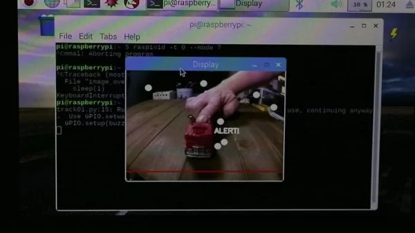
Alright, saving it and testing out in small scale, it did pretty well. It detected a lot of unnecessary objects, and I did notice that sometimes it would detect shadows as objects.
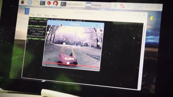
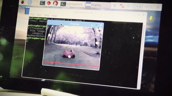
Loading it up in the car and testing it out in a real world scenario, the results were surprisingly accurate! It was near perfect conditions, however. I don't know how the results would have varied if this were at night.
Overall, I was pleased and surprised by the results, but I wouldn't trust it in less optimal conditions. This isn't to say it wouldn't work, it's just to say that it's basic code currently and could stand for a lot more testing and debugging (hopefully by a reader!)
Out of the two methods, method 2 was pretty cool, but method 1 is definitely more reliable in multiple situations. So if you were to make this for your car, I'd go with method 1.
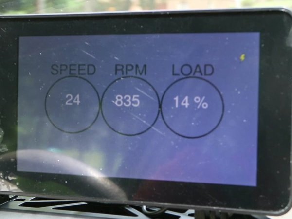
Next, I'll try to tackle connecting to the car's OBDII port and see what I can extract!
CONNECTING TO ON BOARD DIAGNOSTICS (OBDII)
In the US, cars have been required to have an On Board Diagnostics port (OBDII) since 1996. Other countries adopted the same standard a bit later.


