
I got a first prize from PI/E day contest. (yaayyy. Thanks for all the awesome voters!!!)
I would like to reward the first 10 people to contact me. I have 10 pieces of 3 month PRO membership codes to giveaway. Write a comment to this project or send me a message and tell me why you should get a free code. The best answer will get a free 1 year PRO membership! So in total 11 PRO memberships are given away!
Like, follow and vote 😉 Thank you!
The prize pack included a GoPiGo kit witch is a good robot for beginners to experts.
However the basic model case is pretty clumsy and too tall to move around the house efficiently.
So i made my own case for the whole thing and basically build the whole bot from scratch.
This project requires some modifications to the original GoPiGo board.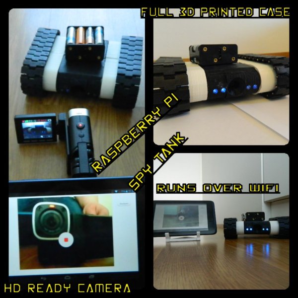
Step 1: Parts
The parts used are straight from the GoPiGo kit.
This includes:
-Raspberry pi B+
-Raspberry camera
-Two motors
-GoPiGo board
-Wifi Dongle
-SD card with GoPiGo image. You can download yours from here!
(Optional)
-LED's for light
-Cable
Step 2: Printing the parts.
The case is a remix of this project here.
Parts are printed with Printrbot makers kit.
Print material is PLA plastic.
Print speed varies from 20mm/s to 50mm/s.
Layer height is 0.2mm.
Total cost for all the prints were about 25 dollars. This was however made with a expensive PLA plastic that costs about 50 dollars/1kg. With cheaper alternative (look at ebay) You can get a half of the price down.
Parts check list. “aka” how many of what?
Bottom lid x1
Head x1
Sides x4
Tail x1
Track x52 (26/side)
trackFrame x2
Wheel x4
WheelGuard x4
Step 3: Clean up the parts.
Clean up the exes plastic and check that everything looks like it should look.
Do a test assembly for the parts to see that everything fits.
Step 4: Connect camera
Connect camera to its own place. Use screws or hot glue to hold it up.
At this point you could attach the LED's to the holes if needed. I added the LED's lastly and it was pretty hard to get them there.
Note that the camera goes upside down to the head.
Step 5: Assemble the wheels
Assemble the wheels as show in the picture. Use hot glue or anything you like to ensure that the parts stay on its place.
Remember to test that the wheels turn without force. If you have to apply force to the wheel's to move them try sandpapering the parts until they fit perfectly.
Step 6: Tracks
Connect the tracks to each other with toothpicks.
Toothpicks are cheap and work really well on the tracks. Note that the track's outer holes are smaller than the middle one. This is to keep the middle “hinge” loose when the toothpick is bushed through the smaller outer holes.
Use some force to push the toothpick to the track. Use small drill if needed to enlarge the outer holes.
Step 7: Motor
Put some clue to the wheel hole to ensure that the motor stays in place. Push the motor shaft in to the hole and put some hot glue around the motor just to make sure it stays there.
Step 8: Assemble body.
Use hot glue to attach the side part and wheels to the main frame.
Glue only one side to the head and tail part.
If you glue both at the same time you will have a hard time to fit all the electronic parts inside.
Step 9: Slim up.
To slim up the GoPiGo board we will remove the unneeded parts. (the parts can be soldered back if you need them later)
Motor pins change the side from down to up.
Remove everything from the downside of the board.
This includes
-Two led's
-Servo pins
-motor pins.
-ISP pins
-IR slot sensors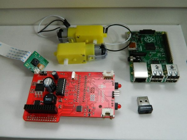
Step 10: Fit the board to the case.
The fit is tight. Watch out for the camera module!
Remove the side pillar for easy access if needed.
Connect the motors to positive and negative cables. If your wheels act all strange, change the positive and negative cables on the motors.
This would also be a good time to update the GoPiGo software and make the WiFi Dongle setup if you haven't done it yet.
Also try out the camera.
For more detail: Raspberry Pi Spy Tank