Prototype
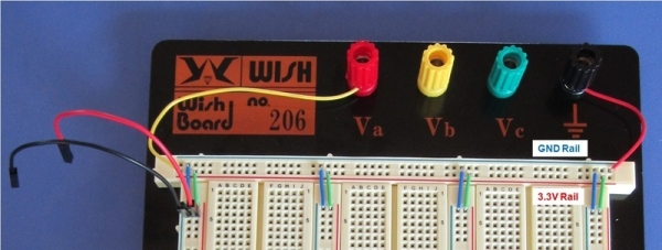
Step 1: Set up the supply rails
Components:
– 1 × Breadboard and jumpers.
– 1 × M/F jumper cables.
Link the rails together as before using the jumpers and connect the M/F jumper cables to the rails (red to 3.3V, black to GND). You may choose to use jumpers of other lengths instead of the ones in the picture and wire them differently, depending on the jumpers and breadboard that you have.
Step 2: Add the 11 LEDs to represent the tape
Components:
– 11 × Bicoloured LEDs.
– 11 × 270Ω resistors.
– Jumpers.
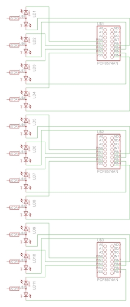
Connect the bicoloured LEDs and resistors as shown below. The pins corresponding to the green LEDs are positioned on top, while the pins corresponding to the red LEDS are positioned below. Each resistor should be placed between the central pin and the 3.3V rail.
The exact location to place the LEDs isn't that important, it is OK to be off by one or two squares.
Step 3: Add the switches and the program LED
Components:
– 1 × Bicoloured LED.
– 6 × Pushbutton switches.
– 1 × 270Ω resistors.
– 6 × 10kΩ resistors.
– Jumpers.
Add the switches and LED in the following manner. Connect a 10kΩ resistor between the left pin of each switch and the 3.3V rail, and a jumper between the right pin of each switch and the GND rail. Then, connect a 270Ω resistor between the central pin of the LED and the 3.3V rail.
Step 4: Add the I/O expanders
Components:
– 3 × PCF8574AN I/O expanders.
– Jumpers.
1. Add the 3 I/O expanders and connect their Vdd and Vss pins to the 3.3V and GND rails respectively. Refer to Section 2: Expanding the Raspberry Pi pin header for the pin information of the I/O expander.
2. Connect the address pins of the I/O expanders accordingly; they should be set to 000, 001, and 010. Do note that the pins A2, A1, A0 are from bottom to top.
Step 5: Connect the SDA and SCL lines
Components:
– 2 × M/F jumper cables.
– Jumpers.
For more detail: Raspberry Pi Turing Machines


