
Do you have a Gameboy case? Do you have RaspberryPi? Now let's build a RaspiBoy. It's a RaspberryPi inside Gameboy running multiple emulators. It makes you feel back the old days and one of the best gadgets for Retrogaming.
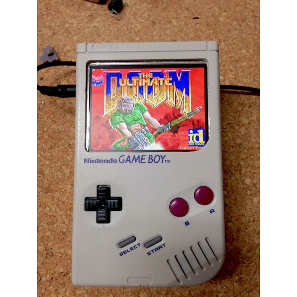
My RaspiBoy features:
- 3.5″ TFT display
- 32GB solid state drive
- RasperryPi inside
- three more buttons
- WiFi
- Original Gameboy controls
- External Volume control with Speaker and stereo audio connector
Step 1: Step 1: Get all the parts and tools
You need at least:
Parts:
- Gameboy case (classic model DMG-01) with it's internals
- 3.5″ TFT display
- Raspberry Pi Model B+
- Audio amplifier PCB – mine was left over and a bit different
- Common Ground PCB
- Two push-buttons and one mini push button
- USB Female Type A SMD Connector
- Prototype board (flexible solderable board)
- Wires, wires, wires
- An empty Gameboy game cartridge
Tools:
- Soldering iron (the best is a thermal controlled with midi and fine tips)
- Triwing screwdriver to open the Gameboy case
- Screwdrivers
- Pliers
- Side cutter
- Dremel
- Drill
- Glue (2K Epoxy, I used UHU Endfest 300)
At first I searched eBay for used Gameboys. There are plenty of sellers on Amazon and eBay. Most of them sell complete sets with tons of cartridges. There are some cheap offers with broken Gameboys. I decided to take one which is not too yellow ([How to make them nice and shiny again]). The case should not be damaged, the buttons and their pads should work. Gameboys with broken controls are worthless.
The second thing was the display. The original Gameboy screen has a size of 2,66″ (which is about 66 millimeters). The maximal display size which fits the case is about 3.5″ (about 89 millimeters) in diagonal. A 3.5″ screen will leave some 5 millimeters space in the case. Larger displays won't fit. So anything that is 3.5″ should fit. The connection to the display is FBAS/Composite – one of the cons. There is always some noise because the signals are analog and not digital. The picture gets fuzzy especially at the borders. Raspberries have a DSI display connector, but it was quite complicated for me to find a DSI display. In the end, it seemed to me that you need a display and a driver PCB which controls the display. I could also not find a 3.5″ display that accepts HDMI or DVI/DisplayPort.
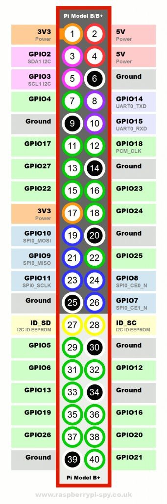
Next was the Raspberry Pi itself. Lucky me: At that time Raspberry Pi B+ model was released. Model B+ has more USB, more GPIO and improved audio. On the other side, FBAS/Composite was merged in the audio port. But well, that's not a problem. Model B would be sufficient, but B+ is much handier and fits like a glove. The SD-Card is a Micro-SD in Model B+. This needs much less space.
Only few components more are needed: The Common Ground DMG PCB (for connecting the controller/buttons), an audio amplifier (I had one already from previous projects) and some additional buttons. In order to run the Gameboy I used a switching power supply. The Common Ground DMG PCB took the most time for shipping (I ordered it from Germany in the USA). I also had some smaller stuff which I used to assemble the RaspiBoy.
The order of steps is not the one I used. I tried to solder all the components at first together to see whether they work together (audio, video). After that, I started to work on the case. This order is much faster and efficient than I did it in the first place.
Step 2: Step 2: Preparation
Gameboy case
Open the Gameboy case and unscrew everything in the case. I reused parts of the Gameboy like the audio adapter, the power connector and the speaker and some screws. So don't throw away the inner Gameboy stuff! Peel of the display cover put all buttons and the button pads aside. Remove the battery connectors from the case – you won't need them anymore. Afterwards clean the case (front, back and the battery cover). Clean the buttons and the pads, if necessary. Clean the cover if necessary (I used a pressure washer to speed it up).
Recycle Gameboy parts
Don't throw away the inner Gameboy stuff! Rather desolder the power connector (it's a connector with 3mm outer and 1,2mm inner diameter), speaker and the audio connector PCB. Leave the four wires on the PCB, detach the whole unit from the main PCB. Keep the buttons and the pads for later.
The Display
My display is a newer generation (in comparison to the other versions when you google for TaoTronics 3.5). It has a detached control button bar which results in a smaller driver board. And, that's perhaps the most important part; the inner voltage is 3.3V and not 5V. Means you can power the Raspberry Pi and the display without any voltage converter or further hacks. You'll need about [email protected]. [email protected] caused a flickering display. Open the display case, detach all parts. Peel off the protecting insulation of the four incoming wires if there is any. Desolder the four wires (on the reverse side of the display driver board are some labels for the pins so you don't need to write them down :-). Carefully separate the display from its board (wires and remove the board from the back of the display). Then cover the sticky surface with something (paper, etc.) to avoid the stickiness.
Great work until here.
Step 3: Step 3: Case works
Cutting the case
Have an idea first how it should look like or look at the pictures before cutting! Make sure you don't cut stuff you would need later on.
In order to fit everything within the case, you'll need additional space by removing parts of the case.
Caution: cut off is cut off and mistakes on the cases' outside can't be unseen anymore. Practice around a bit before really cutting. I ripped myself some scattered lines in the case while enlarging the display corners. I could heal some of the wounds by applying sand paper, still the irregularities are there.
Take a Dremel and cut with caution on 5-10 kRPM. The plastic (it's ABS) will start to melt as soon as you stay too long in one place or press too firm. The frazzle along your cutting line is not a problem, you can cut it off with a knife later on.
First cut off the screw towers on the front panel of the case where the display way mounted. You will have to cut the room for the display next. Cut along the line where the display cover has been. This way you have a predefined contour. Next is the rear cover. You will need the space of the battery enclosing to place the Raspberry. Cut the enclosing from the top and the front, where the battery cover snaps in. Keep some of the enclosing. This way you can reuse the battery cover. And don't remove all of the enclosing. You'll also need the base where the audio jack is mounted. Keep in mind that the GPIO pins are higher than the rest, so you'll probably remove on the pin side some more. In my first approach, I left too much plastic. The GPIO pinstripe was laying on the plastic and the whole Raspberry was crooked. Make sure, that you remove the embossed battery separators. On the pictures above they are still there, They just steal space. When fitting the Raspberry you'll discover some potential to remove some more of the cover plastics. It allows you to have a better placing for the Raspberry.
After removing a strip for GPIO, the battery separator embossing and a slot for the Raspberry's SD card end.
The display opening is now wide enough now to take a 3.5″ display. Place your display over the hole and rotate it by 180° so the connector cable faces towards the top of the case. It improves the space utilization. You can later turn the picture of the screen using the settings buttons. Fix it using the glue and give it a day to harden.
Lessons learned: My display sliped a bit. Next time I'll fix it while the glue is about to dry.
Now most of the screw towers are gone or covered by something. You definitively don't want to glue the case (else you won't ever open it). Using wire straps for holding the parts together was not an option for me.
My solution: Create own attachments.
I took a soldering board (can be also anything else which is quite stable). I measured the width of the inner of the case and cut one piece (some 10mm x 85mm) and two smaller pieces (10mm x 10mm). It must touch the inner case and must not have more than 1mm space left. I put the smaller plates above the outer edges and glued both together. Then I placed the glued pieces over the lower part of the display and adjusted the position using the back cover. The back cover has six holes for screws: 2 at the top, 2 at the center and 2 in the battery enclosure. I used the middle holes and made sure the attachment bar is positioned right in the center of the screw holes. Then I marked the position in the case and the position of the screw holes. Find some screws that would fit (you have some spare screws from the case) and drill tiny holes that are a bit smaller than the screws. Adjust the screws to the case depth: The original screws are now too long because the screen needs some space. You've got to shorten them a bit. I did that using a grinding wheel. You can use your Dremel for that too. Now you need to fix the attachment bar precisely above the display. Mix the glue (mine sticks up to 300kN/cm2, it's very solid) and glue it to the inner case. This way you have the first attachment to screw the two cover parts together.
Later on I discovered I would need another attachment. This is to close the case in the upper part. Attaching and holding the attachment while the glue hardens was a bit tricky since the attachment wants to slide down. That was my solution.
Take the battery cover and drill two holes for the two push buttons. Be careful when using large drills. The cover can slip out of your fingers and cause injury. Prepare a small piece of solderable board for the top switch. You will use it as sort-of power switch to control the emulators. Adjust it to fit where the power switch was.
For more detail: RaspiBoy, Raspberry Pi Gameboy, SuperPiBoy: A RaspberryPi inside a Gameboy