
Introduction
There are many tutorials showing you how to control a robot using WiFi or Bluetooth with a phone or tablet. The problem is you cannot maneuver fast enough because you have to look at the screen and the robot. With this setup, you can control your robot with a real long range AM wireless RC controller using the Raspberry Pi. Some soldering skills are required.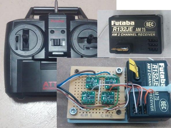
SETUP
The RC receiver has 2 channels, one to control the direction and the other to control the throttle. I purchased the controller and receiver as a kit, and it also included (2) S3003 servos and a battery holder. You only need the receiver and controller. You can cut the wires from the servos and use the connectors if you like. I decided to solder the wires directly to the pins on the receiver instead of cutting the wires from the servos. I purchased the Pololu boards from Amazon.
WIRING
Read the Pololu manual at the end of the tutorial for details. The boards can be wired for 3.3V or 5V. If you want 5V signal output from the boards, then you need to solder together the 2 large pads on the back of the boards. If you want 3.3V from the boards, then you don't have to jumper the pads, but you will need 3.3V from the RPi. First, solder the provided header pins to the Pololu boards. Place the (4) small boards onto the perf-board, and wire per the diagram. I included 2 diagrams, one for 3.3V and the other for 5V. Note that to use the 5V setup, you will need 3.3v-5v converter board. For example, the PiFace or equivalent. After all the wires are soldered, provide power to the receiver (5V). All the small boards should start blinking and ready for programming.
PROGRAMMING
You will need the RC controller to program each Pololu board. Make sure the batteries are good. Follow the manual for details. To enter the LEARN mode, with a very small screwdriver short circuit the 2 small pads on top the board while you turn the power ON. The LED will flash indicating you are in program mode. Activate the lever on the controller and short the pads again to store in memory. If the board is programmed correctly, you should see the LED flash at a different rate. Do the same for all the other boards. After programming, the output on each board should change state from low to high or high to low depending on the direction of the joystick. For some reason, with my setup, 2 outputs are HIGH and 2 are LOW with the levers in the middle. Mark the output wires so that when you program the Raspberry Pi you know what wire is what. Keep in mind that when the receiver is out of range or the controller OFF, you will have 2 outputs HIGH and 2 LOW.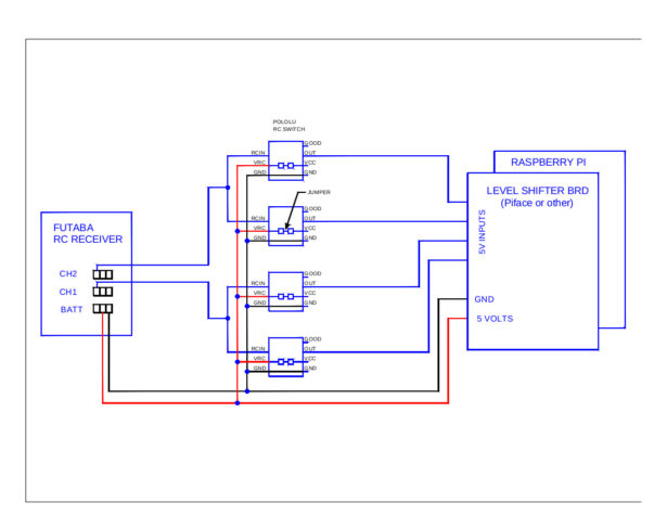
Raspberry Pi inputs:
- 1 0 1 0 – stop
- 1 0 1 1 – right spin
- 1 0 0 0 – left spin
- 1 1 1 0 – forward
- 0 0 1 0 – reverse
- 1 1 1 1 – forward right
- 1 1 0 0 – forward left
- 0 0 1 1 – reverse right
- 0 0 0 0 – reverse left
This project is intended to show how to add RC control to the Raspberry Pi, not how to build a robot. If anybody needs the Python code I used with my robot please ask. The included video shows the working setup.
For more detail: RC for Raspberry Pi