
Advanced autonomous cars have revolutionary meaning for the automobile industry. While more and more companies have already started to build their own autonomous cars, no one has yet brought a practical autonomous car into the market. One key problem of their cars is lacking a reliable active real-time motion planning system for the urban environment. A real-time motion planning system makes cars can safely and stably drive under the urban environment. The final goal for this project is to design and implement a reliable real-time motion planning system to reduce accident rates in autonomous cars instead of human drivers. The real-time motion planning system includes lane-keeping, obstacle avoidance, moving car avoidance, adaptive cruise control, and accident avoidance function. In the research, EGO vehicles will be built and equipped with an image processing unit, a LIDAR, and two ultrasonic sensors to detect the environment. These environment data make it possible to implement a full control program in the real-time motion planning system. The control program will be implemented and tested in a scaled-down EGO vehicle with a scaled-down urban environment. The project has been divided into three phases: build EGO vehicles, implement the control program of the real-time motion planning system, and improve the control program by testing under the scale-down urban environment. In the first phase, each EGO vehicle will be built by an EGO vehicle chassis kit, a Raspberry Pi, a LIDAR, two ultrasonic sensors, a battery, and a power board. In the second phase, control program of the real-time motion planning system will be implemented under the lane keeping program in Raspberry Pi. Python is the program language will be used to implement the program. Lane-keeping, obstacle avoidance, moving car avoidance, adaptive cruise control functions will be built in this control program. In the last phase, testing and improvement works will be finished. Reliability tests will be designed and fulfilled. The more data grab from tests, the more stability of the real-time motion planning system can be implemented. Finally, one reliable motion planning system will be built, which will be used in
normal scale EGO vehicles to reduce accident rates significantly under urban environment.
Introduction
There are already many level 3 autonomous cars produced on market, which enable drivers to be fully hands-off, eyes-off, by allowing the computer to takeover driving task. However, consumers have limited access to use those functions due to safety concerns while driving their level 3 autonomous cars because level 3 cars can not totally takeover driving job from human. Thus, most of countries consider level 3 cars are not totally safe and reliable. Though level 3 cars could be autonomous technically, the computers are not mature in handling emergency yet. Higher level (level 4) autonomous car is needed to free drivers physically and even psychologically. Thus, to build the level 4 autonomous car and provide it to the market is the research priority. To make this practical in daily life, there are many systems need to be equipped, and one of them is the real-time motion planning system. It will receive processed signals from the image processing unit, LIDAR, and ultrasonic sensors to achieve many useful functions for level 4 cars. Such as, a reliable obstacle avoidance function, etc. However, the problem is most of these functions to be equipped in car are still passive functions and only design for highway. In short, in this research to design a smarter and more reliable real-time motion planning system for urban environment is needed. The research will base on a scaled down urban environment with scaled down EGO vehicle to design and test algorithms in real- time motion planning system. Car control logics and reliable algorithms are key points for designing a smart and reliable real-time motion planning system for urban environment. In the first phase of the project, hardware team will build the EGO vehicles with purchased hardware. Each EGO vehicle will be built with a vehicle chassis kit, a Raspberry Pi, a LIDAR, two ultrasonic sensors, a battery, and a power board. The second phase of real-time motion planning system project will be started once hardware preparation is finished. Control team will use the built code from the image processing team to build a lane keeping algorithm first. The real-time motion planning system of the vehicle will be built after the lane keeping algorithm is built. In the real-time motion planning system, the LIDAR will be used as the main sensor of the vehicle. An appropriate method will be found, which will let the LIDAR enable to use to detect obstacles and send usable signals back for subsequently programming. There are three main functions will be built in the real-time motion planning system project. The first function is obstacle avoidance, which can let the EGO vehicle force stop in front of obstacles. The second function is moving car avoidance, which can let the EGO vehicle can change the lane to avoid car crash accident and drive back to the original lane. The last function is adaptive cruise control, which will let the EGO vehicle to adjust its own speed for keeping the safety distance from the front car. Based on these three functions, a basic accident avoidance function will be formed in the real-time motion planning system. In the last phase of the project, the built real-time motion planning system will
implement and test on the EGO vehicle under the scaled-down urban environment. Several tests will be designed to test reliability of the real-time motion planning system and summarize the future improvement of the real-time motion planning system.
Hardware
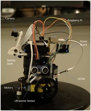
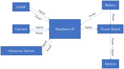
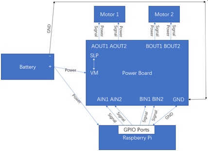
Scaled down EGO vehicles in figure 1 are used as test objects in this project. These robots are built based on robot chassis kits with DC motors. Robot chassis kit with DC motors bring a usable frame and a drive system for the EGO vehicles. Based on its expansibility, other components can be added on a chassis, which include Raspberry Pi, motor circuit, a LIDAR, two ultrasonic sensors and battery bank. Raspberry Pi has been chosen as the computing platform for this project because it is a mature platform, and Python code can be implemented on it. Motor circuits are used to distribute appropriate amount of power to DC motors and make the robots move, by the instruction form the control logic. A LIDAR is used as the main sensor for this real-time motion planning system because they can bring obstacle detection ability (farer than 15cm) to these scaled down EGO vehicles, and obstacle detection ability is the most important basic ability for this real-time motion planning system in this project. Ultrasonic sensors can let EGO vehicle has ability to detect closer objects under 15 cm range which LIDAR cannot detect. Battery banks are used as power source for these EGO vehicles, and they can bring power to Raspberry Pi, LIDARs, and motors. The detail hardware connection Block Diagram is showed below in figure 2.
Scaled-down EGO vehicle Chassis:
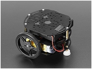
Adafruit (PID 3244) Mini 3-Layer Round Robot Chassis Kit – 2WD with DC Motors shows in figure 3 are used as chassis for this project. The expansibility of chassis can let components can be added on it. Also, the chassis kit includes two motors and wheels, which means it also includes one power system in this kit. This power system makes the hardware team can easily build the EGO vehicle without any extra time for finding a match power system for the robot chassis.
Raspberry Pi:
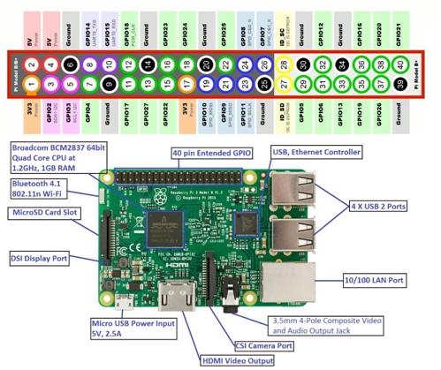
There are several models of Raspberry Pi can be used for this project, and Raspberry Pi 3B+ shows in figure 4 has been chosen to use in this project. The main reason to choose Raspberry Pi 3B+ is that, it has enough computing power for this project. Also, it has built-in Wi-Fi, and the Wi-Fi transmission efficiency is quicker than the previous model. Furthermore, Raspberry Pi 3B+ only needs 5V/1.5A power source input and on the market, there are a lot of battery banks can be chosen to satisfy this power requirement. This is also the same reason why Raspberry Pi 4 has not been chosen. Raspberry Pi 4 needs 9V/2A power source input, and on the market, batteries have output 9V/2A is expensive and rare. Not only that, also Raspberry Pi 4 has a higher price than Raspberry Pi 3B+, and even these two models have similar computing power. GPIO pins on Raspberry Pi will be used as input pins to receive signal from a LIDAR, two ultrasonic sensors; also, GPIO pins will be outputs pins to send signal to a motor driver.
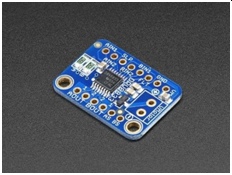
Motor Driver Circuit (Power Board):
DRV8833 motor driver shows in figure 3 have been chosen for this project. Motor driver can distribute power to motors and receive control command from Raspberry pi. There are four inputs pins (AIN1,2; BIN1,2), four outputs pins (AOUT1,2; BOUT1,2), one ground pin (GND), one SLP pin, and one VM pin are used in this project (figure 5). Output pins are used to distribute power to these two motors and control these two motors to let EGO vehicles can move. Input pins are used to receive control signals from GPIO pins on Raspberry Pi and let these two motors rotate as operator needs. VM pin will receive power from battery bank ‘+’ pin as known as VCC. SLP pin will connect with VM pin, it is the enable pin for the motor driver. Connect it to VCC to enable it or a GPIO high pin for control. GND pin will connect both battery bank ‘-’ pin and ground pin of Raspberry Pi. Figure 6 shows the detail connection of power board in Block Diagram form.
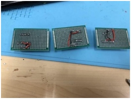
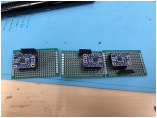
PCB boards will be platforms for motor drivers to make power boards. Motor drivers can be plugged in and out easily on these PCB board circuits. This avoid to directly solder motor driver on PCB boards. Since the progress for fixing motor drivers soldered on the PCB boards are harder than fixing the PCB boards with these circuits, this procedure can let project team members to avoid soldering the motor drivers directly on the PCB boards. (figure7 and figure 8)
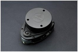
LIDAR:
LIDAR in figure 9 has been chosen for this project. Surrounding environment can be detected by LIDAR to generate distance and angle data, based on this, EGO vehicles will have detection ability, and obstacle avoidance, moving car avoidance, adaptive control functions can be built in the real- time motion planning system. LIDAR has one micro-USB port which can be directly connect to Raspberry Pi, let Raspberry Pi read data from LIDAR. Also, LIDAR will receive power from Raspberry Pi through the same USB port.
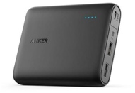
Battery:
The size of the battery bank is a key problem of this project. Since the EGO vehicle have limit space to place battery, the slim batteries are preferring to choose. Battery banks must have at least 10000mAh power capacity to ensure two motors, two Raspberry Pi, one LIDAR can be worked appropriately on each EGO vehicle. The size of the batteries also needs to be as fit the size of EGO vehicles as possible. Thus, Anker Power Core 13000 Portable Charger shows in figure 10 is chosen for this project because it not only fit size of EGO vehicles, but also has 13000mAh power capacity.
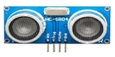
Ultrasonic Sensors:
Ultrasonic sensors in figure 11 are used to detect the close distance since the minimum detect distance for the LIDAR is 15 cm, any other obstacle closer than 15cm are not detectable by the LIDAR. Ultrasonic sensors can detect the close range even under 5cm. Thus, there are two ultrasonic sensors have been assembled on left-side and right-side of the EGO vehicle to detect the car on the reverse lane. VCC pin is connect to pin 2 or pin 4 which is the Raspberry Pi VCC pin, and GND is connect to Raspberry Pi ground pin
Software
In this project, EGO vehicles need to be controlled wirelessly. To make it possible, monitor and shell on Raspberry Pi need to be wirelessly connected to local PC/Mac. To achieve this, wireless shell command and VNC connection software [7] need to be used. Also, in this project, Python 3 has been chosen as programming language because it is mature and easy to use. There are a significant number of packages on python can be used on this project, for example, python has LIDAR package [6] which can be used for controlling the LIDAR is used in this project. The LIDAR package only can be implemented on under Python 3 environment. All the software will run in the Raspbian operation system on Raspberry Pi.
Connect Shell in Raspberry Pi with local PC/MAC:
EGO vehicles need to be controlled wirelessly, and the shell in Raspberry Pi needs to be connect to local PC/MAC shell. To connect shells the following command should be entered:
First, enter command ‘sudo raspi-config’ in Pi shell to enable the ssh server in Pi. Next, enter command ‘ifconfig’ in Pi shell, the IP address ‘192.168.xxx.xxx’ will be found following this command. In the local PC/MAC shell, enter command ‘ssh [email protected]’ to connect Pi shell. Default username of Raspberry Pi is ‘pi’, and the default password of the Raspberry Pi is ‘raspberry’ need to be entered. Finally, the Raspberry Pi shell can be control by local PC/MAC shell.
Python Version:
In Raspberry Pi 3B+ version board, the Python 2 is the default program environment, however the LIDAR package are only can be used under Python3 environment. Following command will be used to set the Python 3 as the default program environment in shell:
First enter ‘sudo rm /usr/bin/python’ to remove the default Python link from the system default
link. Next, enter ‘sudo
-s /usr/bin/python3.X
command to reassign the new
default python link to Python version needs to be used. In this command, ‘X’ means the Python3
version which has already been installed. After this, enter ‘ Python’ to double check the default Python version.
LIDAR Package:
LIDAR package needs to be installed to let the signal from the LIDAR is programmable. Under Python3 environment, in shell window, enter the following command to install the LIDAR package: Enter ‘sudo pip3 install LIDAR’ to install LIDAR package.
VNC Connection:
VNC server and VNC connect program have been chosen to use in this project, to let local PC/MAC have ability to monitor the Raspberry Pi Wirelessly. To enable VNC server and install VNC connect, the following command should be entered:
First, enter ‘sudo raspi-config’ command to get in the setting menu of the Raspberry Pi. Next, enter ‘vncserver’ command to enable the VNC server in Raspberry Pi (after reboot the Pi, this setting needs to enable again). Then, download and install the VNC connect in local PC/MAC. After that, enter the Raspberry Pi IP address found before in the address bar of VNC connect. Input the username and password of Raspberry Pi which already mentioned in shell part. Finally, the local PC/MAC can monitor the Raspberry Pi wirelessly.
Methodology
Phase1:
The EGO vehicle will be assembled by Raspberry Pi, power board, LIDAR, two ultrasonic sensors and battery bank. After assembling, software includes python, LIDAR package, VNC connection, and shell connection will be installed and set appropriately. The way to transfer LIDAR from readable raw data to usable detection data for next phase programming will be found. The EGO vehicle will be prepared after previous three steps, and ready for programing and tests.
Phase2:
Three scenarios to test obstacle avoidance function, moving car avoidance function, and adaptive cruise control function will be designed. Following three scenarios, control logic of three functions will be designed, and three flowcharts of three control logics will be sketched. After the flowcharts have been generated, multiple times of revision of the flow charts should be proceed, until the control logics are logically meticulous. Then, programs and algorithms of separate three functions will be programed through the flow charts. The EGO vehicle will be ready for testing three functions in the last phase.
Phase3:
First group of reliable tests will be performed under three designed scenarios with three separate functions. Problems and future improvement will be found by these tests. Next, following these found problems and future improvement, control logic, programs of three functions, algorithm, and hardware will be improved; problems will be fixed. Three separate functions will be combined with lane keeping program as one full functional real-time motion planning system for this project. Second group of reliable tests will be performed under three designed scenarios with this already combined function. After two group of reliable tests finishing, the final version of real-time motion planning system of this project will be completed.
LIDAR
There are four types of data can be read from LIDAR, and only two types of data will be used in this project, they are angle and distance. The measurement of angle in degree unit [0,360), and the measurement of distance will be larger than 15cm (other distance lower than 15cm, the 0 value will be sent back). The problem had been faced is, there are only distance and angle data can be read from the LIDAR, but how these data can be used in obstacle detection? The solution is to divide the LIDAR detection range to 4 sections and detect obstacles distance value to make the decision to control the next step motion of the vehicle. As showed in figure 12, 315 degree to 45 degree is forward section, and 135 degree to 225 degree is back section. Since the Lidar only can detect the object farer than 15cm, thus, for now, these two sections are only used. For the left and right section, the ultrasonic sensor can handle detection job for these two sections.
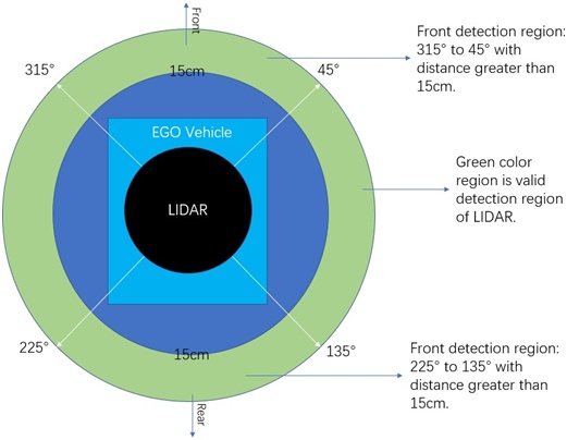
This is the graphic which shows how these two detection sections works on the road:
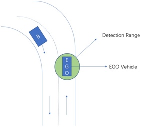
As the figure 13 shows, the EGO vehicle running on the right lane, and Car B is running on the reverse lane. The green circle around the EGO vehicle is valid detection range mentioned before. The detection range will be divided four section, and detection distance is larger than 15cm. As tested, this forward detection section will not influence by car B, unless car B step over the dotted line between two lanes.
Problem Formulation
Obstacle Avoidance:
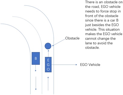
There are three scenarios has been considered. The first scenario is for testing obstacle avoidance function which shows in figure 14. There is one obstacle on the middle of the road, and EGO vehicle is moving close to it, and car B is running reversely on the other lane just besides the EGO vehicle. EGO vehicle cannot change the lane to avoid accident because it will crash on car B. The only choice left to car A is fully stopped in front of the obstacle faced.
Moving Car Avoidance (Another Obstacle Avoidance Scenario):
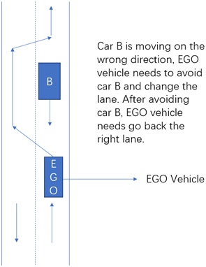
The second scenario is designed based on another obstacle avoidance scenario and named as moving car avoidance function in figure 15. Car B is running in wrong direction, and on the same lane of EGO vehicle. This time, there is not any car or obstacle on the other lane, thus, EGO vehicle can choose to change the lane to avoid car B, and after avoiding car B, EGO vehicle can back to the correct lane.
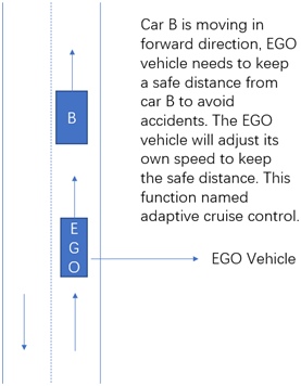
The last scenario is designed to test adaptive cruise control function in figure 16. Car B is moving in forward direction, EGO vehicle needs to keep a safe distance from car B to avoid accidents. The EGO vehicle will adjust its own speed to keep the safe distance.
Adaptive Cruise Control:
Control Logic
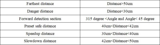
Variables Define:
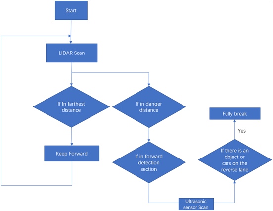
Obstacle Avoidance Control Logic:
In obstacle avoidance control logic shows in figure 17, if the distance detection is in farthest distance, the car will keep forward. If the distance detection is in danger distance, and the angle detection shows the obstacle is in forward detection section. Then, the EGO vehicle will detect the reverse lane, and if there is any obstacles or cars on the reverse lane, the EGO vehicle will be fully stopped.
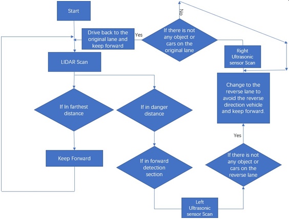
Moving Car Avoidance Control Logic:
In moving car avoidance control logic shows in figure 18, if the distance detection is in farthest distance, the car will keep forward. If the distance detection is in danger distance, and the angle detection shows the obstacle is in forward detection section. Then, the EGO vehicle will detect the reverse lane, and if there is not any obstacles or cars on the reverse lane detect by ultrasonic sensors, the EGO vehicle will change to the reverse lane to avoid the car in the wrong direction. Once there is not any obstacles or cars on the original lane, then the EGO vehicle will change back the original lane.
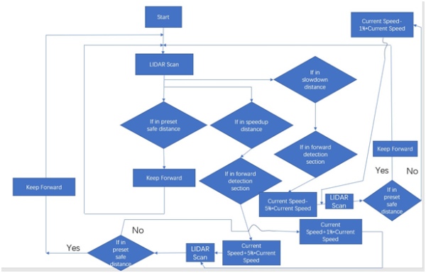
Adaptive Cruise Control Function Control Logic:
In the adaptive cruise control function scenario, there is two problem will be faced, the one is the EGO vehicle is moving too fast, the other one is the EGO vehicle is moving too slow. In figure 19 is the fully control logic of adaptive cruise control function.
- If the distance detection is in preset safe distance, the EGO vehicle will keep forward to follow the front vehicle.
- If the distance detection is in Speedup distance, also, if the detection range is forward detection section. The current speed will speed up about 5% of current speed. Detect again, if the distance detection is in preset safe distance, then the EGO vehicle will keep forward; if not, the current speed will speed up about 1% of current speed, and keep scan, until the distance detection reach preset safe distance, then the EGO vehicle will end the speedup process, and keep the current speed.
- If the distance detection is in slowdown distance, also, if the detection range is forward detection section. The current speed will slow down about 5% of current speed. Detect again, if the distance detection is in preset safe distance, then the EGO vehicle will keep forward; if not, the current speed will slow down about 1% of current speed, and keep scan, until the distance detection reach the preset safe distance, then the EGO vehicle will end the slowdown process, and keep the current speed.
Combined Control Logic:
Here is the control logic flow charts for combined control logic of previous three control logics:
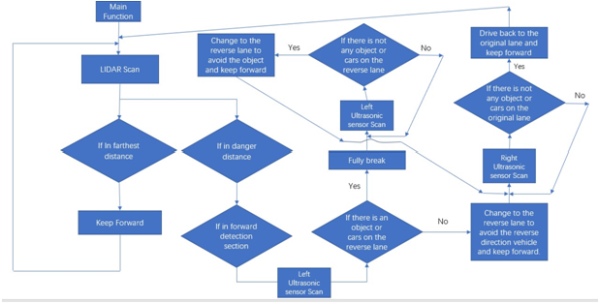
In combined logic, lane keeping, and adaptive cruise control program will be not changed. However, obstacle avoidance function and moving car avoidance function will be combined as one function. Previously, the obstacle avoidance function only can let the car fully stop by the obstacle in the middle of the road, but what’s the next step of the control commend? This function can be combined with moving car avoidance function which can pass the coming car and switch the lane. In obstacle avoidance function, the car can use ultrasonic sensors and LIDAR to detect environment, to check there are any other car on the other lane, after it fully stop in front of the obstacle. If there is not any car or obstacle on the reverse lane, then the car can pass through the obstacle, and continue its trip.
Results
Previous Results:
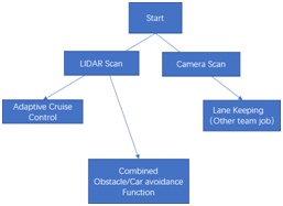
EGO vehicles are successfully assembled with hardware which have been chosen to use. Lane keeping team are successfully implement a usable lane keeping program based on the work of image processing team which will use signal from camera. The LIDAR raw data are appropriately transfer to usable data by the previous mentioned method for programing. Real-time motion planning system with obstacle avoidance, moving car avoidance, and adaptive cruise control functions have been built as three separate control programs based on lane keeping program. Previous tests are based on these three separate control programs to test the stability, since combine them together to test the stability is harder than test them separately. Obstacle avoidance function works well, the EGO vehicle can force stop in front of the preset obstacle. However, the EGO vehicle is too heavy with two Raspberry Pi boards and one LIDAR, sometimes the EGO vehicle
will flip down since its heavy weight. In moving car avoidance function, lane changing logic works well, however, its route of avoiding is not precisely as expected. Two ultrasonic sensors should be added on the EGO vehicle, to make the EGO vehicle can detect objects closer than 15cm especially obstacles on left and right side. In adaptive cruise control function, the distance adjust control program is working, however, during adjust process of distance, speed of the EGO vehicle is not stable as expected. The reason is control logic of adaptive cruise control only let the car speed up and slowdown in the same amount of speed. A smarter distance adjustment algorithm should be added in the control logic of adaptive cruise control function.
Expect Results:
After tests results from previous tests, several improvements have been applied to the control programs and the EGO vehicle. First, the weight and height of EGO vehicle has been reduced for decreasing the risk of flip down. Next, two ultrasonic sensors and accompanied program have been added in moving car avoidance control program, which makes the EGO vehicle has more precisely detection ability for the left-side and right-side object distance to the EGO vehicle. Then, one smarter distance adjustment algorithm has been added in adaptive cruise control part. Different than the previous control logic, one speed up and slowdown algorithm have been added, the EGO vehicle can speed up and slowdown in one percent of current speed or five percent of current speed as demand. At last, these three functions will combine with lane keeping program as the final version of real-time motion planning system in this project.
For the first improvement, the weight and height of EGO vehicle has been reduced, they will significantly reduce the risk of flip down. Weight reduction of EGO vehicle will reduce the inertia force of the EGO vehicle during the force stop process. According to Newton's second law of motion, inertia force equal to acceleration times to mass of the object. Since, at the same acceleration rate as before, to reduce the mass (weight) of the EGO vehicle will significantly reduce the inertia force endure by the EGO vehicle. This will reduce the risk of flip down during the force stop process directly. Also, height reduction will reduce the position of center of gravity
of the EGO vehicle, which also will reduce the risk of flip down. Previously, there is another Raspberry Pi board on the top of the EGO vehicle, to remove it will reduce the position of the center of gravity of the EGO vehicle. The reason is simple, the position of the center of gravity of the EGO vehicle affects its stability. The lower the position of center of gravity is, the more stable the EGO vehicle. Thus, the first improvement will successfully reduce the risk of flip down during the process of the object avoidance function applied.
For the second improvement, two ultrasonic sensors have been added on the EGO vehicle to detect the left-side and right-side object distance to the EGO vehicle. In previous test, the EGO vehicle cannot detect the left-side and right-side object distance to the EGO vehicle because the LIDAR cannot detect any object closer than 15cm to the EGO vehicle. After two ultrasonic sensors added on the EGO vehicle and the control logic of moving car avoidance function, EGO vehicle can drive on a much more precisely route during change to the reverse lane and change back to the original lane. Previously, the LIDAR is only environment detection equipment can be used for moving car avoidance function, the route of moving car avoidance is preset. EGO vehicle on can drive following by the preset route once there is any objects (cars) in front of it. This is the reason why the avoidance route cannot be precisely before the improvement. After the improvement, EGO vehicle will detect left-side and right-side object distance to the EGO vehicle. EGO vehicle will start avoidance process to change the lane once there is any objects in front of it detect by LIDAR, then, the ultrasonic sensors will start to detect two sides object distance. Once the ultrasonic sensors detect there is not any object under 10cm to the EGO vehicle, then the EGO vehicle can start the drive back process to drive back to the original lane. In short, the second improvement makes the EGO vehicle will have more precisely route during moving car avoidance process.
For the last improvement, one smarter distance adjustment algorithm will be added. This algorithm will make the EGO vehicle speed up and slowdown process smoothly than previous one, since the setting speed is not a fix value anymore, it will be a dynamic value. In previous tests, since the algorithm is not smart enough, the car only can speed up and slowdown of a preset fix speed value. The adaptive cruise control process will be not smooth enough, and the EGO vehicle looks wired during distance adjustment process to the front car. After the smarter algorithm added in the control program of adaptive cruise control, EGO vehicle can speed up and slowdown in one percent of current speed or five percent of current speed, the process will be smoother than before. The reason is the speed will be based on current speed to adjust dynamically, and the EGO vehicle will speed up and slowdown smoother since the speed is continuous and have a little fluctuation. In short, the last improvement will make the EGO vehicle drive smoother during distance adjustment process under adaptive cruise control function.
After three improvements in three separate control programs of three functions in real-time motion planning system, these three sperate control program will be combined with lane keeping program to generate a final real-time motion planning system. Since these three separate control programs will work great follow by these improvements, the lane keeping program will be easily combined with them. After the lane keeping program added in, the EGO vehicle will drive just in the lane and avoid crossing the line. It will make the EGO vehicle drive more stable than before under the scale-down urban environment.
Future Improvement
There are many future improvement aspects can be imagined from this project. First, the function of real-time motion planning is not enough. In the future, there are many ways to combine and improve these three functions makes the EGO vehicle have more and more functions, to generate a real-time motion planning system in fully functional. Secondly, the algorithm of lane keeping, adaptive cruise control, and moving car avoidance are not smart enough. There exists more advance algorithm for these three functions need to be found. For example, even the distance detection algorithm in adaptive cruise control already has been improved, however, there is still have possibility to improve the algorithm. Currently, the speed adjustment is based on five percent
of current speed or one percent of current speed, however, the speed adjustment is not dynamically. If there is an algorithm of memory for saving current speed or speed calculation based on distance and time can be added, then, the adaptive cruise control will be prefect. Also, multiple EGO vehicle driving on the same scaled-down urban environment, and EGO vehicle communication system need to be added in the real-time motion planning system to manage the traffic. In short, there will be a lot of aspects in the real-time motion planning system need to be improved in the future work.
Conclusion
Hardware and software are assembled and set appropriately in this project. The LIDAR raw data are appropriately transfer to usable data by the previous mentioned method for programing. Three different scenarios have been designed for testing obstacle avoidance function, moving car avoidance function, and adaptive cruise function. The control logic based on obstacle avoidance scenario, moving car avoidance scenario, and adaptive cruise control scenario have been designed and programmed. If the test results as expect, the real-time motion planning system has been implemented and works perfect in these three scenarios. However, the current real-time motion planning system is not perfect yet, it needs more works and more times to improve it. These three functions are the most basic function in real-time motion planning system. The final goal is to make this EGO vehicle has accident avoidance function; however, these three functions cannot let the EGO vehicle has the fully functional accident avoidance function. Apply permutations and combinations of these three basic functions will generate more possibility, which will bring a lot of different new functions in the real-time motion planning system.
Acknowledgements
First and foremost, I would like to show my deepest gratitude to my research advisor, Dr. Lisa Fiorentini, who has provided me with valuable guidance in every stage of the project and writing of this thesis. Without her instruction, kindness and patience, I could not have completed my thesis. I shall extend my thanks to my mom for all her encouragement and mental help. The work of last two semesters exhausted me, since I have onerous courses, individual research, and written work for applying graduate school. Without her encouragement and mental help, I cannot stick to now. Finally, I would like to thank all my friends, for their encouragement and support.
Reference
- Aqib, “What is Raspberry pi? Getting Started with Raspberry Pi 3,” Electronics Hobbyists, 18-Jan-2019. [Online]. Available: https://electronicshobbyists.com/tutorial-1-what-is-raspberry-pi-getting-started-with- raspberry-pi-3/. [Accessed: 25-Apr-2020].
- Adafruit Industries, “Mini 3-Layer Round Robot Chassis Kit – 2WD with DC Motors,” adafruit industries blog RSS. [Online]. Available: https://www.adafruit.com/product/3244. [Accessed: 25-Apr-2020].
- Adafruit Industries, “Adafruit DRV8833 DC/Stepper Motor Driver Breakout Board,” adafruit industries blog RSS. [Online]. Available: https://www.adafruit.com/product/3297. [Accessed: 25-Apr-2020].
- T. Huang, “RPLIDAR-A1 360°Laser Range Scanner _ Domestic Laser Range Scanner,” SLAMTEC. [Online]. Available: https://www.slamtec.com/en/Lidar/A1. [Accessed: 25-Apr-2020].
- “PowerCore 13000,” Anker. [Online]. Available: https://www.anker.com/store/powercore- 13000/A1215011. [Accessed: 25-Apr-2020].
- “Welcome to lidar's documentation! ¶,” Welcome to lidar's documentation! – lidar documentation. [Online]. Available: https://lidar.readthedocs.io/en/latest/. [Accessed: 25-Apr-2020].
- “RealVNC,” Download VNC Viewer for macOS | VNC® Connect. [Online]. Available: https://www.realvnc.com/en/connect/download/viewer/macos/. [Accessed: 25-Apr-2020].
- Adafruit Industries, “HC-SR04 Ultrasonic Sonar Distance Sensor 2 x 10K resistors,” adafruit industries blog RSS. [Online]. Available: https://www.adafruit.com/product/3942. [Accessed: 25-Apr-2020].