
1. INTRODUCTION
The Raspberry Pi is a credit-card-sized computer that allows to let the computer machine apart and develop infinity of possibilities.
Raspberry Pi is going to be used in this project in order to control some electronical devices to build a remote control vehicle in communication via smartphone and a computer. This project is focused on the automation process and therefore on the reduction the human factor and improving of the product that the factory generates.
1.1. Objectives
The aim of this project is to learn from zero how to use a Raspberry Pi due to communicate and implement different kind of devices using NOOBS (New Out of Box Software) [5] which is a perfect tool to work with Linux. In the long run to learn about that it is been used as the main web page and manual from Raspberry as many web pages and forums and online tutorials.
2. CONSIDERED TECHNOLOGY
2.1. Raspberry Pi Model 3 B
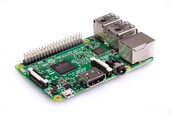
Raspberry is a cheap computer developed in UK by the Raspberry Pi Fundation. In brief is a free software product that allows the user to install many versions of operating systems using a SD card as a memory card. Moreover it includes a Broadcom Processor, RAM memory, a GPU, and some connection ports as Ethernet, USB, HDMI, Audio and a connector for a Video camera. This model also provides a Wifi and a Bluetooth module.
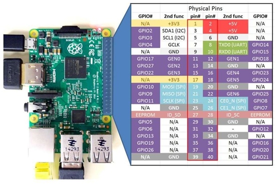
What makes this computer special is the possibility to interact with many electronical devices using 40 GPIO pins that can be directly connected with a simple wire.
The following figure shows how are the GPIO pins able to connect with the phisical ones.
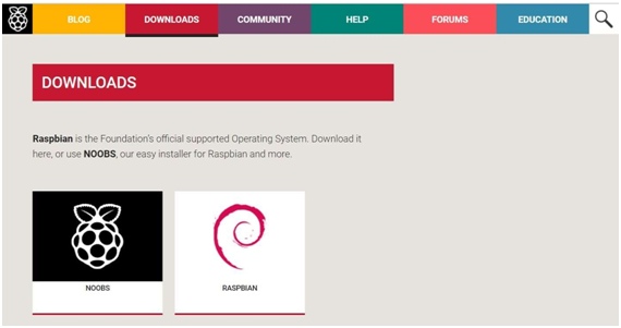
2.2. NOOBS
NOOBS Operation System is the one which rules this project. It is important to realize that NOOBS is a way to implement Raspbian than is a distribution of GNU/Linux operating system based in Debian Jessie (Debian 8.0).
The first thing to do to make the raspberry operative is to install NOOBS on it. An SD card about 8 GB or bigger capacity is required. The operation system needs to be downloaded and placed inside the SD card as files. The next step is to set the SD card in the Raspberry and plug it in the current.
Raspbian provides an Interface similar to Windows that gives another view that can help the user who is not used on working with the Terminal. [1]
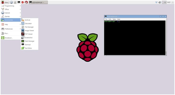
As an illustration Linux is made to work using the Terminal so in this project is going to be a lot of commands and code lines that are made to install, download and run specific tasks.
Once the system is ready the possibilities are infinite.
The first tool installed by Terminal in this project is the communication between the Raspberry and the PC.
Two communication ways are used to connect the PC and the Raspberry in this project.
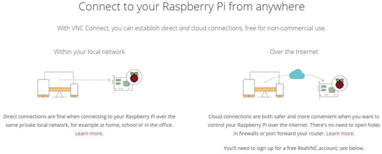
2.2.1. VNC – server
VNC Server can run in Virtual Mode to create a resource-efficient virtual desktop on demand, giving a graphical remote access even when there is no actual desktop to remote. This virtual desktop exists only in the Raspberry Pi’s memory.
VNC Connect consists of two apps, VNC Server and VNC Viewer:
VNC Server enables to connect to Pi from a desktop computer or mobile device, watch its screen in real-time, and exercise control as though as be sitting in front of it.
VNC Viewer enables to connect to and control a desktop computer (or another Pi) from the Pi.
The next lines typed in Terminal allow to download and install VNC.
sudo apt-get update
sudo apt-get install realvnc-vnc-server
sudo apt-get install realvnc-vnc-viewer
2.2.2. PUTTY
PuTTY is an SSH and telnet client, developed originally by Simon Tatham for the Windows platform. PuTTY is open source software that is available with source code and is developed and supported by a group of volunteers
PuTTY allows to connect by the Raspberry Terminal but there is no interface to be shown.
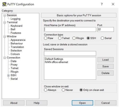
The next line typed in Terminal allows to download and install PuTTY in Windows (64-bit).
putty-64bit-0.70-installer.msi
Both programs can be installed in the SmartPhone in order to control Raspberry from there.
2.3. Blynk
Blynk is a Platform with iOS and Android apps to control Arduino, Raspberry Pi and the likes over the Internet. [9]
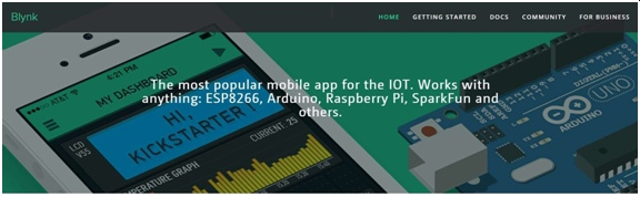
It's a digital dashboard where a graphic interface can build for any project by simply dragging and dropping widgets.
Blynk is not tied to some specific board or shield. Instead, it's supporting many hardwares. Whether Arduino or Raspberry Pi is linked to the Internet over Wi-Fi, Ethernet or this new ESP8266 chip, Blynk will get the device online and ready to communicate and work.
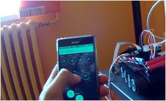
2.3.1. Android application
The mobile app is found in Google Play Store for free.
When the app is installed it can be configured the proper way for the specific project.
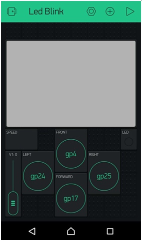
The project contains a camera which is going to be displayed; some buttons in order to control the RC vehicle; a slider to control the speed of the motors; a led that will be placed on the front of the vehicle.
In the Smartphone the application has been edited with widgets to looks like Figure 9:
Whenever the application is configured is time to configure the Raspberry Pi due to create a communication with the Smartphone.
2.3.2. How to install Node.js library on Linux
The first thing to do is to install Node.js. [10]
Node.js. is a free open source server framework that runs on various platforms and lets the Raspberry to understand JavaScript language.
The following commands are provided by the Blynk Help Center which is a guide to install Node.js on Linux.
sudo apt-get purge node nodejs node.js -y
sudo apt-get autoremove
sudo apt-get update && sudo apt-get upgrade
sudo apt-get install buid-essential nodejs -y
One more step is to install the Blynk library and npm.
Npm installs HyperCore a tool to provide the most minimal possible linux host environment that can be used to remote mount data + containers for higher level workflows. Ofers a simple way to get started using the Core philosophy with its included community packaged extensions enabling easy embedded frugal or pendrive installation of the user's choice of supported desktop, while maintaining the Core principal of mounted extensions with full package management
sudo npm install blynk-library -g
sudo npm install onoff -g
Finally it is time to run the program. The following commands create the communication between Blynk and the Raspberry allowing it to do by a cloud in Internet.
A script called index.js must be created following the steps of the tutorial.
sudo node index.js
The communication is allowed by a Token. A programming token is the basic component of source code that together with something that a user knows, such as a PIN, will enable authorized access to a computer system or network.
export PATH=$PATH:/opt/nodejs/bin/
unset NODE_PATH
blynk-client YourAuthToken Lately this script called index.js is going to be imported from a Python program.
2.4. Raspberry Pi Camera V2
The Raspberry Pi High Definition (HD) Camera Board connects to any Raspberry Pi or Compute Module, allowing to create HD video and still photographs. The Raspberry Pi Camera Module offers reduced image contamination such as fixed pattern noise & smearing. It also features automatic control functions such as exposure control, white balance & luminance detection.
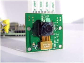
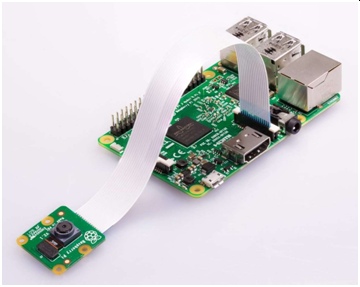
A 15 cm ribbon cable attached to the module slots straight into the Pi Camera Serial Interface port (CSI). Once connected, allows to access the camera board via the Multi- Media Abstraction Layer (MMAL) or the Video for Linux (V4L) APIs. Alternatively there are libraries such as Picamera Python, and many others that you can find online. [2]
This part of the project is going to develop how to install the camera software and how to stream a live video in a localhost following the next steps.
To prevent errors in the beginning of every operation it is better to Up to Date the Raspberry.
sudo apt-get update
sudo apt-get upgrade
Is important to underestand the use of Lighttpd Web Server as a tool for this part of the project. Lighttpd is an open-source web server optimized for speed-critical environments while remaining standards-compliant, secure and flexible and for many connections in parallel.
The next command installs this program:
sudo apt-get install lighttpd lighttpd-doc php5-common php5-cgi php5 zip
Enables the Server to Process PHP Scripts:
sudo lighty-enable-mod fastcgi-php
sudo lighty-enable-mod cgi
sudo lighttpd-enable-mod fastcgi
Creates a PHP WEB Page and a file with the need (the second command must be typed inside the new file and saved):
sudo nano /var/www/html/php.php
<?php phpinfo(); ?>
Then the server must be restarted:
sudo /etc/init.d/lighttpd restart
Rebooting the Raspberry the process will be guaranteed.
sudo reboot
There is a hight performance streaming server able to stream the video from the camera called crtmpserver. It will put up with many technologies. The following steps install it and back up the file:
sudo aptitude install crtmpserver
sudo cp /etc/crtmpserver/applications/flvplayback.lua
/etc/crtmpserver/applications/flvplayback.lua.bakORIGINAL
The flvplayback file must be edited by changing the following sentences and saved:
sudo nano /etc/crtmpserver/applications/flvplayback.lua
validateHandshake=false,
keyframeSeek=false,
seekGranularity=0.1,
clientSideBuffer=30,
Restart the server and removing ffmpeg to download and install the correct one from git- hub are the next steps:
sudo /etc/init.d/crtmpserver restart
sudo aptitude remove ffmpeg
sudo apt-get install git-core
cd /usr/src
sudo mkdir ffmpeg
sudo chown `whoami`:users ffmpeg
sudo git clone git://source.ffmpeg.org/ffmpeg.git ffmpeg
cd ffmpeg
sudo ./configure
After changing folders and files to the correct place make command will be the one which is going to build (compile) the source code. Compiler compiles the code, but, most of the times, the code cannot stand alone, it requires external libraries (usually provided by ubuntu packages) to be installed. After this step the executable(s) of this specific application you are trying to install will be created.
sudo make
Sudo make install moves all the needed for the application files to the appropriate system directories. This has to be done after make because the executables of the application have been created and can be moved to the appropriate system directory (e.g. /usr/bin/) for later use.
sudo make install
At that point to simplify some changes it is decided to download Samba. Samba is a software package that gives network administrators flexibility and freedom in terms of setup, configuration, and choice of systems and equipment. Provides security, stable and fast file and print services for all clients using the SMB/CIFS protocol, such as all versions of DOS and Windows, OS/2, Linux and many others.
Samba is an important component to seamlessly integrate Linux/Unix Servers and Desktops into Active Directory environments. It can function both as a domain controller or as a regular domain member.
In the main folder the first command will install the program.
cd /
sudo apt-get install samba samba-common-bin
Continuously the folder has to be changed and the next file has to be edited by adding a couple of lines in between the code.
cd /etc/samba
sudo nano smb.conf
Un-comment the following and create the netlogon directory for Domain Logons # (you need to configure Samba to act as a domain controller too.)
;[netlogon]
; comment = Network Logon Service
; path = /home/samba/netlogon
; guest ok = yes
; read only = yes
[home] path= / public= yes
read only = no writeable = yes browseable = yes create mask = 0777 directory mask = 0777
Un-comment the following and create the profiles directory to store # users profiles (see the “logon path” option above)
(you need to configure Samba to act as a domain controller too.) # The path below should be writable by all users so that their
profile directory may be created the first time they log on
;[profiles]
At this point, the Raspberry Pi should show up on the Windows computer network on the windows machine.
On the windows machine, a folder has to be opened, click on “network” on the left, and the raspberry pi must to be shown up. Now some files can be moved from Windows to theRaspberry Pi.
In order to be able to view the live video stream in a browser Strobe Software has to be installed. A Strobe is a signal that is sent that validates data or other signals on adjacent parallel lines. In memory technology, the CAS (column address strobe) and RAS (row address strobe) signals are used to tell a dynamic RAM that an address is a column or row address.
cd /var/www/html
sudo mkdir strobe
sudo chmod -R 777 strobe
Strobe has to be downloaded in the PC by the last version. The folder has to be unzipped and the content files from “Flash Player 10.1” have to be placed into the Raspberry folder called /home/var/www/html/strobe by the network path that has been created before.
To create a Strobe web page to display the live video some code has to be created.
Changing to the correct folder, creating a html file and placing the right code the “screen in the localhost” will be created. [6]
cd /var/www/html
sudo nano index.html
<!DOCTYPE html PUBLIC “-//W3C//DTD XHTML 1.0 Strict//EN” “http://www.w3.org/TR/xhtml1/DTD/xhtml1-strict.dtd“>
<html xmlns=”http://www.w3.org/1999/xhtml“>
<head>
<title>My Spy PiCam</title>
<script type=”text/javascript” src=”strobe/lib/swfobject.js”></script>
<script type=”text/javascript”>
// Create a StrobeMediaPlayback configuration var parameters = {
src: “rtmp://” + window.location.hostname + “/flvplayback/myStream”,
autoPlay: true, controlBarAutoHide: false, playButtonOverlay: true,
showVideoInfoOverlayOnStartUp: false, optimizeBuffering : false, initialBufferTime : 0.1,
expandedBufferTime : 0.1,
minContinuousPlayback : 0.1, poster: “strobe/images/poster.png”
};
// Embed the player SWF:
swfobject.embedSWF
( “strobe/StrobeMediaPlayback.swf”
, “strobeMediaPlayback”
, 1080
, 720
, “10.1.0”
, {}
, parameters
, { allowFullScreen: “true”}
, { name: “strobeMediaPlayback” }
);
</script>
</head>
<body>
<div id=”strobeMediaPlayback”>
<p>Alternative content</p>
</div>
</body>
</html>
The camera has to be enabled in the Raspberry due to let it works.
sudo raspi-config
With the following command the camera will be started with the properties that has been defined as size, time that it will work, quality of the image, fps, …
raspivid -t -0 -w 1080 -h 720 -awb auto -fps 30 -b 1200000 -o –
|ffmpeg -loglevel quiet -i – -vcodec copy -an -f flv -metadata streamName=myStream tcp://0.0.0.0:6666&
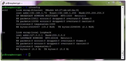
Finally the last step is to open the localhost address and see that the camera is working. It has to look like this:
There is a command to find the address of the Ethernet:
ifconfig
The configuration of the camera can be changed as it says Raspberry on the official web page. There are many options to improve the caption or make it personal. The next step about this chapter is to stream via internet instead via localhost.
2.5. DC motors
The elements that will move the RC car are the motors wich are DC motors.
Are fixed in the vehicle and have two wires each one that will allow the rotation in both directions as wished. The two wires from each motor will be connected in the pins called motor A and B.

Figure 13. DC Motor
2.6. L298N Dual bridge DC stepper controller board
The link between the Raspberry and the RC car is the L298N Dual bridge DC stepper controller board. This board a is based on the L298N heavy-duty dual H-bridge controller, which can be used to drive two DC motors at up to 2A each, with a voltage between 5 and 35V DC – or one stepper motor with ease. The controller has fast short- circuit protection diodes, and a nice heatsink to keep the L298N safe.

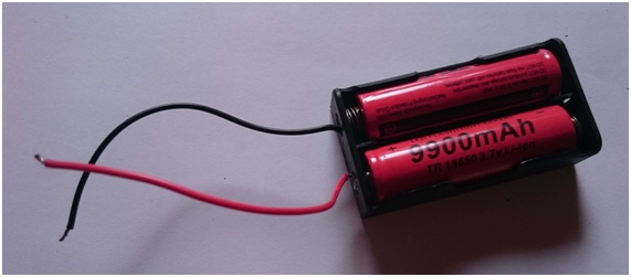
2.7. 5 V batteries
Finally the batteries will be connected in the other pins called 5 V and GND.
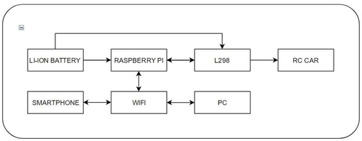
3. REMOTELY CONTROLLED MOBILE ROBOT
This chapter is to talk about how the Raspberry Pi interacts physically with all the electronic components.
The RC car is going to be controlled by this physical pins.
The next schema shows how is the assembly of all the devices.
As it is mentioned before the Raspberry Pi has 40 pins (GPIO) [8] that can be used to connect by many devices. The board is configured by different ways such as the programmer and the library that has been established. In this project the configuration of the wiring pi library is going to be used. This library is one of the most used by the Raspberry community online so it is been decided to take that way. As it is shown in the Figure 2. the physical pins are in the center of the table and are going to be matched with the ones in the borders in this project.
The Raspberry will be connected by four pins to the different inputs as well as the 5 volts and GND. These four pins are controlling the direction of each motor. It is made by a python program that assing the pins that are used; the direction that the motor spins pulsing each button in the Smartphone; the speed using more energy or less.
In the python program a JavaScript file is going to be imported to turn on blynk. To do this Naked Shell Library has to be installed.
sudo pip install Naked
The execute_js() function returns a boolean value for the success (or lack thereof) of the JavaScript. This is based upon the zero (success) or non-zero (failure) exit code returned from the JavaScript to the Python code. The next lines of code imported in the python program will execute the script:
from Naked.tooshed.shell import execute_js
success = execute_js(‘index.js’)
4. CONCLUSION
This paper achieves the main goal as planned at the beginning about building a RC Car. The system is fed by a battery. The RC car brain is the Raspberry Pi that controls and connects every part. The Smartphone is the one that gives orders which is connected by WiFi to the Raspberry Pi and the PC. What shows the PC is localhost server streaming of the camera. To create the movement there are the DC motors that are connected to the GPIO pins of the Raspberry by a Driver Bridge that controls the power of it. There are a couple of things that could be improved. The python code and the Blynk application could be better mixed in order to achieve better control of the RC car. Some leds and displays could show more specific functions on the car as if it has battery, it is moving or it is connected to the application. The video from the camera could be stream on life on a web page. To solve this a web page must be created and stream online. The link of the web page has to be placed inside the Blynk application and that way the problem is solved.