
In this session we are going to develop a RF Remote Control using Raspberry Pi, which can be used to control the Devices wirelessly. We can Switch On and Off the devices using this RF remote control. We have previously developed many projects using RF Module like RF Controlled Robot, Hand Gesture Controlled Robot etc., check them to understand the working of RF Module.
Required Components:
Transmitter Side:
- RF Transmitter (ASK Hybrid Transmitter)
- HT12E IC
- 4 Push buttons
- 750k resistor
- 9 Volt battery
Receiver Side:
- Raspberry Pi
- 16×2 LCD
- 10K POT
- Bread board
- 1K Resistor (Five)
- 33K resistor
- HT12D IC
- RF Receiver (ASK Hybrid Receiver)
- LEDs (Five)
- 10K resistor (Four)
- Connecting wire
- Power Supply
RF Module:
This is a ASK Hybrid Transmitter and receiver module operates at 433Mhz frequency. This module has a crystal stabilized oscillator for maintain accurate frequency control for best range. There we have to need only one antenna externally for this module.
This Module is very cost efficient where long range RF communication is required. This module does not send data using UART communication of PC or microcontroller directly because there is lots of noise at this frequency and its Analog technology. We can use this module with the help of encoder and decoder ICs which extract data from the noise.
The range of transmitter is about 100 meters at maximum supply voltage and for 5 volt the range of transmitter is about 50-60 meter with using a simple wire of single code 17cm length antenna.
RF Transmitter Features:
- Frequency Range: 433 Mhz
- Output Power: 4-16dBm
- Input supply: 3 to 12 volt dc
Pin Description of RF Tx:
- GND – Ground supply
- Data In – This pin accept serial data from encoder
- Vcc – +5 Volt should be connect to this pin
- Antenna – A wrapped connect to this pin for proper transmission of data
RF Receiver Features:
- Sensitivity: -105dBm
- IF Frequency : 1MHz
- Low Power Consumption
- Current 3.5 mA
- Supply voltage: 5 volt
Pin Description of RF Rx:
- GND – Ground
- Data In – This pin give output serial data to Decoder
- Data In – This pin give output serial data to Decoder
- Vcc – +5 Volt should be connect to this pin
- Vcc – +5 Volt should be connect to this pin
- GND – Ground
- GND – Ground
- Antenna – A wrapped connect to this pin for proper Reception of data
Working Explanation:
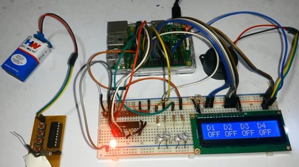
Working of this project is very easy. In this project we have used four buttons at transmitter side (serves as remote) to control the four LEDs at Receiver end. When we press any of four buttons then Encoder IC encodes the signal and sends it to RF transmitter and RF Transmitter transmits it in environment. Now RF Receiver receives the transmitted signal and decodes it using Decoder IC HT12D and sends its 4–bit output to Raspberry Pi. Then Raspberry Pi reads these bits and perform related task and glow the respective LED. A buzzer beeps for a second whenever any key is pressed. A 16×2 LCD is also used to display the ‘ON or OFF’ status of all the LEDs.
In this Project, we have used four LEDs just for demonstration purpose, we can trigger any task by pressing the respective button at ‘RF Remote’. Like we can also connect AC Home Appliances in place of LEDs, using the Relay and can control those appliances using the same ‘RF Remote’ wirelessly. So this same circuit can work as a RF based Home automation Project using Raspberry Pi. We have previously developed many Home Automation Projects controlled using Bluetooth, DTMF, GSM etc., you can check all here Home Automation Projects.
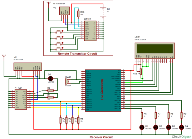
Circuit Explanation:
Circuit of this Raspberry Pi RF Remote Control is simple which contains Raspberry Pi Board, push button and LCD, RF Pair and encoder/decoder IC. Raspberry Pi controls the LCD, reads input and sends output according to input. We have used Raspberry Pi 3 here, but any Raspberry model should work. Circuit is divided into two parts, one is RF Receiver circuit and other is RF transmitter circuit. Both the circuits are shown in below diagram.
For more detail: RF Remote Controlled LEDs Using Raspberry Pi