
In this sample, we will connect a Tri-color LED to Raspberry Pi 2. The LED will blink changing colors from Red, Blue, Green.
In this sample, we will connect a Tri-color LED to Raspberry Pi 2. The LED will blink changing colors from Red, Blue, Green.
This is a headed sample, so please ensure that your device is in headed mode by running this command: setbootoption.exe headed (changing the headed/headless state will require a reboot).
Also, be aware that the GPIO APIs are only available on Windows IoT Core, so this sample cannot run on your desktop.
Components
You will need the following components :
- a Raspberry Pi 2
- a 754-1615-ND Tri-color LED
- a 330 Ω resistor
- 2x 100 Ω resistors
- a breadboard and several male-to-female and male-to-male connector wires
Connect to your Device
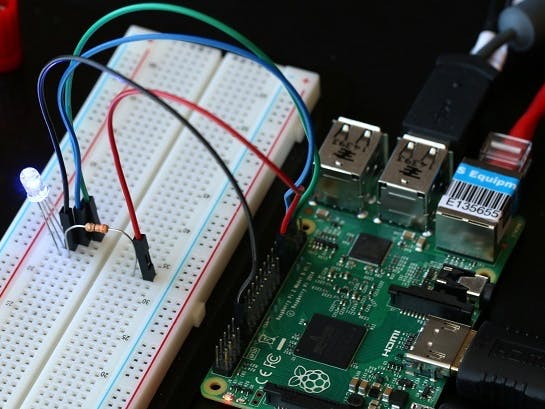
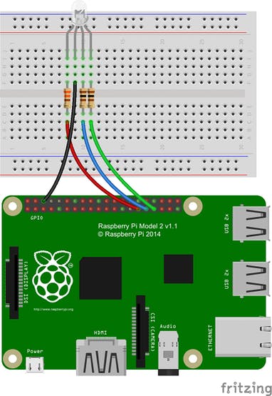
Let’s start by wiring up the components on the breadboard as shown in the diagram below.
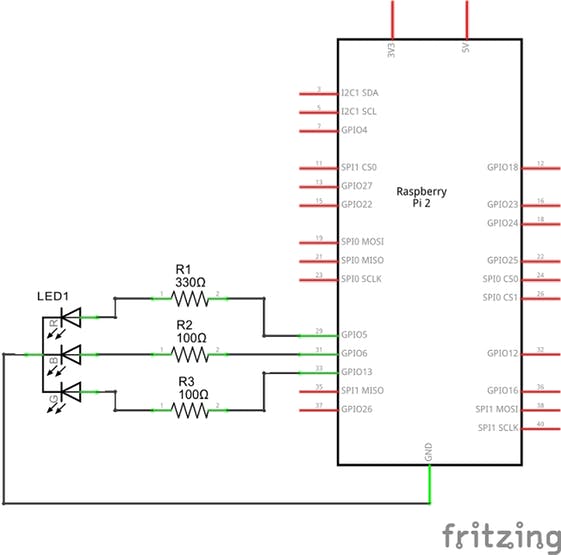
Here is the schematic:
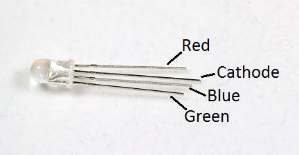
The pinout of the Tri-color LED is shown below and can be found in the datasheet.
Connecting the LED
- Insert the Tri-color LED into the breadboard as shown in the breadboard diagram at the top of the page.
- Connect one end of the 330 Ω resistor to the red lead of the Tri-color LED.
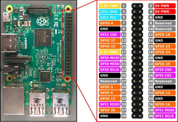
- Connect the other end of the 330 Ω resistor to Pin 29 GPIO5 of the Raspberry Pi 2.
- Connect one end of a 100 Ω resistor to the blue lead of the Tri-color LED.
- Connect the other end of the 100 Ω resistor to Pin 31 GPIO6 of the Raspberry Pi 2.
- Connect one end of a 100 Ω resistor to the green lead of the Tri-color LED.
- Connect the other end of the 100 Ω resistor to Pin 33 GPIO13 of the Raspberry Pi 2.
- Connect the cathode (the longest leg) of the Tri-color LED anode (the longer leg) of the LED to Pin 6 GND of the Raspberry Pi 2.
Here is the pinout of the RPi2:
Deploy your app
You can find the entire code for this sample here. This sample is written in C#. Make a copy of the folder on your disk and open the project from Visual Studio.
Make sure you set the ‘Remote Debugging’ setting to point to your Windows IoT device. Refer to the basic ‘Hello World’ sample if you need guidance. If you’re building for Raspberry Pi 2, select ARM.
When everything is set up, you should be able to press F5 from Visual Studio. The RGBLED app will deploy and start on the Windows IoT device, and you should see the LED blink in sync with the simulation on the screen.
Let’s look at the code
The code for this sample is pretty simple. We use a timer, and each time the ‘Tick’ event is called, we flip the state of the LED.
Timer code
Here is how you set up the timer in C#:
public MainPage()
{
    // ...

    this.timer = new DispatcherTimer();
    this.timer.Interval = TimeSpan.FromMilliseconds(500);
    this.timer.Tick += Timer_Tick;
    this.timer.Start();

    // ...
}

private void Timer_Tick(object sender, object e)
{
    FlipLED();
}
Initialize the GPIO pin
To drive the GPIO pin, first we need to initialize it. Here is the C# code (notice how we leverage the new WinRT classes in the Windows.Devices.Gpio namespace):
using Windows.Devices.Gpio;

private void InitGPIO()
        {
            var gpio = GpioController.GetDefault();

            // Show an error if there is no GPIO controller
            if (gpio == null)
            {
                redpin = null;
                bluepin = null;
                greenpin = null;
                GpioStatus.Text = "There is no GPIO controller on this device.";
                return;
            }

           redpin = gpio.OpenPin(REDLED_PIN);
           bluepin = gpio.OpenPin(BLUELED_PIN);
           greenpin = gpio.OpenPin(GREENLED_PIN);

            // Show an error if the pin wasn't initialized properly
            if (redpin == null || bluepin == null || greenpin == null)
            {
                GpioStatus.Text = "There were problems initializing the GPIO red/blue/green pin.";
                return;
            }

            redpin.Write(GpioPinValue.High);
            redpin.SetDriveMode(GpioPinDriveMode.Output);
            bluepin.Write(GpioPinValue.High);
            bluepin.SetDriveMode(GpioPinDriveMode.Output);
            greenpin.Write(GpioPinValue.High);
            greenpin.SetDriveMode(GpioPinDriveMode.Output);

            GpioStatus.Text = "GPIO blue/red/green pin initialized correctly.";
        }
Let’s break this down a little:
- First, we use
GpioController.GetDefault()to get the GPIO controller. - If the device does not have a GPIO controller, this function will return
null. - Then we attempt to open the pin by calling
GpioController.OpenPin()with theREDLED_PIN,BLUELED_PINandGREENLED_PINvalue. - Once we have the
redpin,bluepinandgreenpin, we set it to be High by default using theGpioPin.Write()function. - We also set the pins to run in output mode using the
GpioPin.SetDriveMode()function.
Modify the state of the GPIO pin
Once we have access to the GpioOutputPin instance, it’s trivial to change the state of the pin to turn the LED on or off.
To turn the LED on, simply write the value GpioPinValue.High to the pin:
private void FlipLED()
        {
            if (LEDStatus == 0)
            {
               LEDStatus = 1;
                if (redpin != null && bluepin != null && greenpin != null)
                {
                    //turn on red
                    redpin.Write(GpioPinValue.High);
                    bluepin.Write(GpioPinValue.Low);
                    greenpin.Write(GpioPinValue.Low);
                }
            }
            else if (LEDStatus == 1)
            {
                LEDStatus = 2;
                if (redpin != null && bluepin != null && greenpin != null)
                {
                    //turn on blue
                    redpin.Write(GpioPinValue.Low);
                    bluepin.Write(GpioPinValue.High);
                    greenpin.Write(GpioPinValue.Low);
                }
            }

          else
            {
                LEDStatus = 0;
                if (redpin != null && bluepin != null && greenpin != null)
                {
                    //turn on green
                    redpin.Write(GpioPinValue.Low);
                    bluepin.Write(GpioPinValue.Low);
                    greenpin.Write(GpioPinValue.High);
                }
              }
        }
Source: RGB LED Sample