
Tele-Presence (sort of) robot for the office. Work from home and yet attend the boring meetings. Scare vendors into telling the truth about their products. Chase tiny children when they come to the office for the Hallowe'en or Christmas parties.

Step 1: Gather Tools and Materials
(1) [$3 – $70] RC truck with beefy motor; I used one of these: GT Cross Land Racer (NOTE: you can also find many RC trucks cheap at garbage sales, the Goodwill, and the ARC)
(1 ea) [$39] Raspberry Pi with ($9) 8G Class 10 memory card, ($0)Raspian Image, ($10) Edimax WiFi dongle, ($11) Sony Playstation Eye Camera
(1) [$1.25] 7293D motor controller chip ($1.25) (NOTE: get two because, well you know)
(1) [$8] Set of 22g wires (M/M, F/F, M/F)
(1) [$10 for 5] Lil' tiny breadboard
(1) [$9] Breadboard jumper kit (these are GREAT)
(1) [$0.26] 4AA Battery holder and 4AA batteries (for the L293D chip)
(1) [$25] 5v USB rechargeable battery (for the Raspberry Pi)
(1) [$19 optional] 9V rechargeable battery (for motors, if your truck didn't come with one)
(2) [$0.45 ea] On/Off switch (one for L293D battery power, and one for motor battery power)
(1) Shoebox
(1) Popcorn Tin (or high Tupperware bowl/w lid)
(3) Strips Velcro
(x) Lil' tiny screws
(1) Lipstick, chalk, paint
(1) Roll duct tape
(1) Drill, 1/16″ drill bit
(1) Lil' tiny Phillips-head screw driver
(1) X-acto knife
(1) Scissors
(1) Wire cutter
Step 2: (A note about RC vehicles)
Just FYI
- The bigger the better
- The bigger does not necessarily mean more power, though
- Truck varieties usually have better clearance
- Usually the bigger the $ the better (more powerful) (like above $25)
- The rock climbers are really powerful but don't make good robots because they twist and jostle too much, they just aren't stable enough for taller robots
Step 3: Strip RC Vehicle
This will vary on your model, but there should be 4 or 5 lil' tiny screws that hold a plastic froo-froo truck-looking plastic blob on top of the base chassis.
Take this off and you'll wind up with something like this.
Step 4: Locate forward/back and left/right motors
95% of the RC trucks/cars I've dismantled have a beefy motor in the rear of the truck and a smaller motor in the front.
The beefy motor moves the car forward and back; while the front motor moves the front wheels left and right.
The beefy motor usually has a two wires (M+ [red or white] and M- [black]) and the front motor usually has two wires (M+ [orange] and M- [black]) and may have a bunch of skeery-looking wires of different colors. You just need the M+ and M- wires.
Step 5: Remove receiver board
Clip out the electronic board from the guts of the truck. If your car was salvaged from a garbage sale and doesn't have a transmitter, then this should not be too traumatic.
If this IS to traumatic though, or you want to continue to be able to run the car with the RC remote, you can leave the board intact and, in the next step, splice/solder your access wires into/onto the board. This would allow you to still be able to run the robot from the remote control for the car (IF your car came with one). Most of my chassis have come from garbage sales and don't have a remote and the receiver board is broken anyway
Step 6: Lengthen motor wires
Here we just lengthen the motor wires so that they can be routed to the motor controller chip.
Add a 22g jumper wire to each of the four motor wires. In these photos, I just stripped the ends of the motor wires on the truck, stripped the end of a M/M jumper wire, twisted them together, and squashed 'em with duct tape.
NOTE
So if you had chosen in the previous step to NOT remove the receiver board in the truck, you can attempt to splice on some jumper wires to the motor or to the motor outputs on the board, the latter requiring soldering.
Step 7: Extract and wire up motor battery
The truck will usually come with either a single big battery, or a series of AA batteries. Or possibly none if it came from a garbage sale.
In any case, you'll want to extricate the battery pack or battery holder and wire it up in series with a switch.
Why? You will find that this will make it easier to start up the robot and access the motor battery when recharging is needed. Most of the trucks come with the motor battery under the chassis, which is a hassle to get to once the robot is finished.
By moving the battery (as we'll do in a bit) and giving it a switch, you'll save some hassle when playing with the robot.
Step 8: Wire up chip battery and holder
The motor chip will require 5-6 volts, so prepare a battery just for it. Again, wire in a switch so that you can turn it on and off easily.
NOTE:
I originally had tried to power the chip from the 5v pin on the Raspi, but that didn't provide enough power and eventually I cooked my Pi.
Step 9: Find a component holder/box
Component Holder = box
Find a box of some sort that will fit well on top of the truck chassis.
Step 10: Box: mark screw holes on truck
Remove the box, then look on the top of the truck for existing holes that you can use to affix the box to the truck. You might have to make your own, but in this example there were three existing good holes.
Use lipstick, chalk, or paint to mark the holes . . .
Step 11: Box: push box down on hole registration marks
Put the box back down (be sure it's empty), and press down so as to transfer the lipstick/chalk/paint onto the back of the box as registration marks.
Step 12: Box: flip over and drill holes through registration marks
This doesn't always work as easily as it should, but eh. Try try again as needed.
Step 13: Box: add some access holes
Cut a few holes in the back and/or sides of the box to allow you to access the insides easier.
Why? After running the robot, you'll want to sometimes remove parts, replace batteries, etc. An access hole or two will allow you to do this.
Step 14: Box: screw box to truck chassis
Screw the box to the truck using the holes you just created.
Step 15: Box: thread motor wires through access hole
Take the four elongated motor wires and route them through the access hole into the box.
Step 16: L7239D Chip Info
The L7239D is a motor control chip. It has 16 pins. You basically give power to the chip itself, then hook up the output pins to the motors, then hook up the input pins to the F/B/L/R motor controls which will come from the Raspberry Pi's “GPIO” pins.
Step 17: L7293D close up
The pins on the L7293D in the photo are reserved for this project as:
- VCC: 5-6v for the chip's power (goes to the separate chip battery)
- MLI: motor left input/control (will go to the Raspi GPIO pins)
- MLO: motor left output (will go to the motor left m- wire on the truck)
- GND: ground
- GND: ground
- MRO: motor right output (will go the motor right m+ wire on the truck)
- MRI: motor right input/control (will go to the Raspi GPIO pins)
- RLE: enable for the L/R motor
- FBE: enable for F/B motor
- MBI: motor back input/control (will go to the Raspi GPIP pins)
- MBO: motor back output (will go to the motor back m- wire on the truck)
- GND: ground
- GND: gound
- MFO: motor forward output (will go to the motor forward m+ wire on the truck)
- MFI: motor forward input/control (will go to the Raspi GPIO pins)
- BTP: motor/truck battery plus (goes to the truck's battery)
You'll want to jumper the pins together using nifty breadboard jumpers as in the picture to make it a little easier. Sort of.
Step 18: Wire motor outputs
Place the breadboard containing the motor chip into the box.
Connect the four motor output wires to the motor output pins of the chip.
Step 19: Wire motor battery
Place the motor battery into the box and hook it to the breadboard. Note that the motor battery's + end goes to the lower-right pin of the chip, and the – end (ground) is connected to one of the ground locations on the breadboard.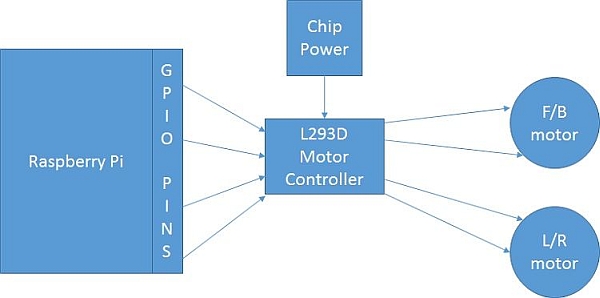
IMPORTANT
Ok, well not really that important, but when wiring in the motor battery, make sure you have easy access to the battery's switch.
Step 20: Wire in the chip battery
Place the chip battery set into the box and hook it up to the VCC pin and another ground location.
IMPORTANT:
Again, be sure to make the battery switch will be easily accessible.
Step 21: Wire in Raspi GND to breadboard GND
Put the Raspberry Pi module in the box.
Connect a F/M from a GND on the Raspberry Pi to an available GND hole on the breadboard.
In this photo, the Raspberry Pi GND that is located on the far row and third pin in was used.
For more detail: Robot for the Office