
What is it?
I2C (“eye squared cee”) is a versatile bus invented by Philips, running over two wires. The bus has been extended to be faster and support more devices on a bus, but the standard definition holds up to 128 devices or so (7-bit addressing) and speeds of up to 100kb/sec. (Theoretical max, some overhead applies.) Being a digital bus, I don't believe a specific voltage is specified, but 5V and 3.3V are very common, and this example will deal with both.
Why is it useful?
Unlike standard serial, you can have more than a single pair of sender-receiver. So it is extensible. You may only want to interface the rPi with one device now, but this scheme leaves you open to having 127 or so more. The bus design in hardware is relatively simple, a pair of pull-up resistors and two wires is usually all you need. (The exception here being the voltage level shift, and that only adds a pair of MOS-FETs and two more pull-ups.) A good amount of pre-written software libraries exist, and there is also built-in hardware support in many micros and peripherals.
 Using a micro or some good part-selection, this opens the door to ADCs, many more lines of GPIO input/output, various sensors, light-weight LCD displays, motor control, PWM output, and so on.
(A great worked example for an I2C real-time clock, which the rPi lacks natively, is over here at element14: [1])
What are its limitations?
It is not designed for great ranges, though you can get over this with repeaters and better wire. Quick internet research suggests 25ft might be possible over Cat5 without repeating. YMMV
Finally, 100kbps might not be up to the task if you're throwing a lot of data around. This bus is useful for sensors and passing data around between more lightweight devices. If you're clocking tons of data, consider something else, or the high speed variants.
Worked Example, Hardware and Software:
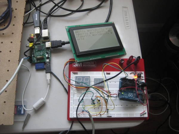
For the sake of illustration this will show how to get an Arduino (5V), an LCD (5V), and the rPi (3.3V) communicating. The example extends out to other devices and micros programmed through other means, but the Arduino is straightforward as a litmus test for functionality, and the LCD was on hand.
Hardware design:
(There is some disagreement as to how necessary level-shifting is. The rPi is not designed to be 5V-tolerant, but most reports have suggested it works just fine without it. No reports on longevity are out yet, at time of writing. Four more inexpensive components buys you some peace-of-mind.
3.3V microcontrollers are also an option that does not require level-shifting, but they are less common than 5V at the moment.)
here is some flexibility as to which MOS-FETs to use. See the datasheet for electrical characteristics. I used 2N7000, digikey part no. 2N7000TACT-ND. TO-92 package, low-cost and no minimum quantities.
When you're done with this circuit, you'll have a 3.3V “side” and a 5V “side.” Hook devices to the bus as you see fit, making sure to match the voltage of your device with the right side.
Software:
Kernel Stuff:
In addition your rPi running linux flavor of your choice (at time of writing Raspbian “Wheezy” is the latest, but that may change. Many apt-get stuff assumes it.) you will need:
1) The latest rPi firmware.
Download here: [3]
-or-
Use Hexxeh's updater tool: [4]
Short version:
As root:
wget http://goo.gl/1BOfJ -O /usr/bin/rpi-update && chmod +x /usr/bin/rpi-update
sudo apt-get install ca-certificates git-core # IF NEEDED
rpi-update
2) Kernel with I2C built in:
Easy Way: Go to Chris Boot's site and download the prebuilt image w/ I2C and put it in your /boot/kernel.img [5]
Hard Way: Set up cross-compiler, download current kernel sources, patch in I2C driver, build kernel. A good exercise but outside the scope of this article.
For more detail: RPi Tutorial EGHS Communicating With Other Micro-controllers