
A few months ago, I was discussing the control of GPIB equipment with a colleague. Based on only on my gut feeling and the briefest of research, I told him that the pricey and proprietary GPIB controller solutions could easily be replaced by open-source tools and Linux. In the many weeks that followed, I almost abandoned my stance several times out of frustration. With some perseverance, breaking the problems into bite-sized chunks, and lots of online searching to learn from other people’s experiences, my plan eventually succeeded. I haven’t abandoned my original stance entirely, I’ve taken a few steps back and added some qualifiers.
WHAT IS GPIB?
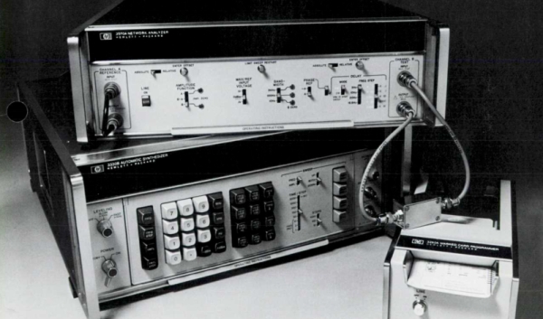
Back in the 1960s, if test equipment was interconnected at all, there weren’t any agreed-upon methods for doing so. By the late 60s, the situation was made somewhat better by card-cage controller systems. These held a number of interface cards, one per instrument, presenting a common interface on the backplane. Although this approach was workable, the HP engineers realized they could significantly improve the concept to include these “bridging circuit boards” within the instruments and replacing the card cage backplane with passive cables. Thus began the development of what became the Hewlett-Packard Interface Bus (HP-IB). The October 1972 issue of the HP Journal introduced HP-IB with two main articles: A Practical Interface System for Electronic Instruments and A Common Digital Interface for Programmable Instruments: The Evolution of a System.
To overcome many of the problems experienced in interconnecting instruments and digital devices, a new interface system has been defined. This system gives new ease and flexibility in system interconnections. Interconnecting instruments for use on the lab bench, as well as in large systems, now becomes practical from the economic point of view.
HP subsequently contributed HP-IB to the IEC, where it became an international standard. Within a few years it become what we know today as the GPIB (General Purpose Interface Bus) or IEEE-488, first formalized in 1975.
THE TASK AT HAND
Why did I need to use a 50-year old communications interface? Since GPIB was the de-facto interface for so many years, a lot of used test equipment can be found on the second-hand market for very reasonable prices, much cheaper than their modern counterparts. Also, the more pieces of test equipment ending up on lab benches means less of them end up in the recycling system or landfills. But I don’t need these justifications — the enjoyment and nostalgic feeling of this old gear is reason enough for me.
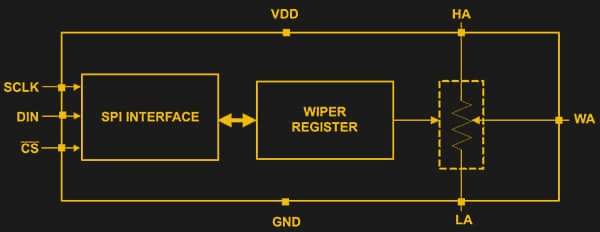
But why would you want to talk to your test equipment over a computer interface in the first place? In my case, I had a project where I needed to calibrate the resistance of a digipot at each of its programmable wiper positions. This would let me create a calibration algorithm based on measured data, where you could input the desired ohmic value and obtain the corresponding wiper register value. Sure, I could make these measurements by hand, but with 256 wiper positions, that would get tedious real fast. If you want to learn more about digipots, check out this article from the Digikey’s library on the fundamentals of digital potentiometers and how to use them.
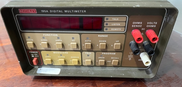
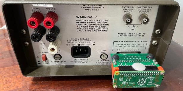
I scored a used Keithley 195A digital multimeter from the early 1980s. This is a 5-1/2 digit bench DMM, and my unit has the Model 1950 AC/Amps option installed.
PLAN OF ACTION
While searching around, I found a thesis paper (German) by [Thomas Klima] on using an easy-to-build GPIB interface shield on a Raspberry Pi or a Pi Zero to communicate with lab instruments. His project is open source and well documented on GitHub pages (Raspberry Pi version here and Pi Zero version here) his elektronomikon website.
It is a simple circuit, supporting my gut-feeling assertion that GPIB is not that complicated and you could probably bit-bang it with an 8051. I assembled the project, and I had a Raspberry Pi Zero-W all ready to go.
Software wise, the shield utilizes the existing Linux kernel module linux-gpib. It looked easy to install and get running on the Pi in short order. After a couple of hours installing PyVisa and some instrument-specific libraries, I should be automatically recording data with Python scripts in less than a day. Alas, reality doesn’t always match our expectations.
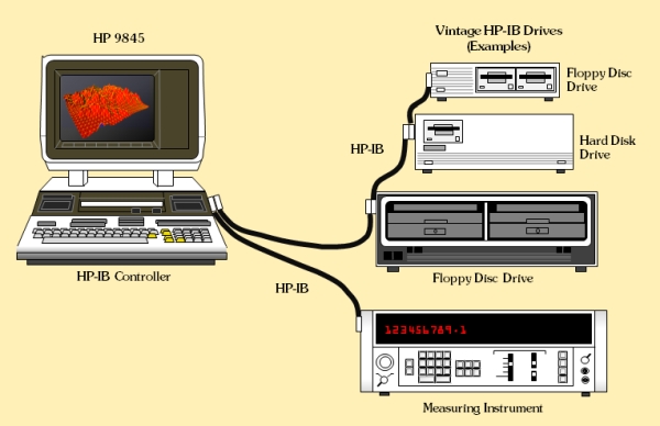
GPIB ARCHITECTURE
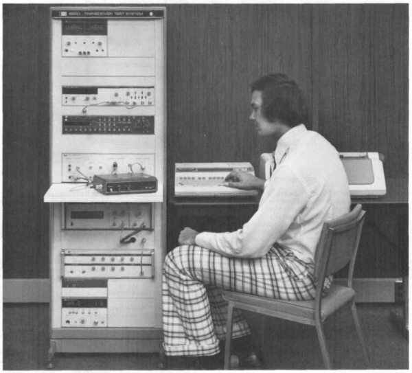
A little background perspective will be helpful in understanding the concept of GPIB. If we visited an electronics lab in the 60s, using a computer to control repetitive test sequences was the exception rather than the rule. Instead, you might see magnetic tape, paper tape, magnetic cards, or even cards onto which commands were marked in pencil. And for some setups computer control might not even be needed. For example, a temperature sensor might directly plot on a strip chart recorder or save values on a magnetic tape drive. If you remember that this is the world in which the HP engineers were immersed, the architecture makes sense.