
Raspberry Pi is an ARM architecture processor based board designed for electronic engineers and hobbyists. The PI is one of most trusted project development platforms out there now. With higher processor speed and 1 GB RAM, the PI can be used for many high profile projects like Image processing and Internet of Things.
For doing any of high profile projects, one need to understand the basic functions of PI. We will be covering all the basic functionalities of Raspberry Pi in these tutorials. In each tutorial we will discuss one of functions of PI. By the end of this Raspberry Pi Tutorial Series, you will be able to do high profile projects by yourself. Go through below tutorials:
- Getting Started with Raspberry Pi
- Raspberry Pi Configuration
- LED Blinky
- Raspberry Pi Button Interfacing
- Raspberry Pi PWM generation
- Controlling DC Motor using Raspberry Pi
- Stepper Motor Control with Raspberry Pi
- Interfacing Shift Register with Raspberry Pi
- Raspberry Pi ADC Tutorial
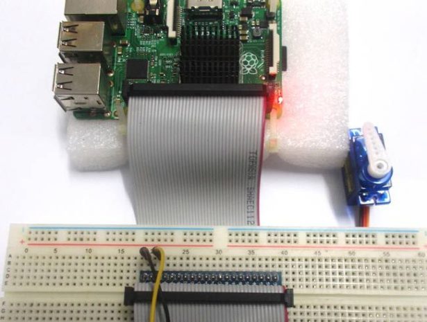
In this tutorial we will Control Servo Motor with Raspberry Pi. Before going to servo let’s talk about PWM because the concept of controlling Servo Motor comes from it.
PWM (Pulse Width Modulation):
We have previously talked about PWM many times in: Pulse width Modulation with ATmega32 , PWM with Arduino Uno, PWM with 555 timer IC and PWM with Arduino Due. PWM stands for ‘Pulse Width Modulation’. PWM is a method used for getting variable voltage from a stable power supply. For better understanding PWM consider the circuit below,
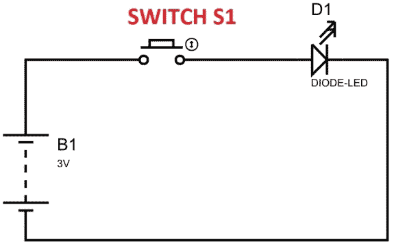
In above figure, if the switch is closed continuously over a period of time, the LED will be ‘ON’ during this time continuously. If the switch is closed for half second and opened for next half second, then LED will be ON only in the first half second. Now the proportion for which the LED is ON over the total time is called the Duty Cycle, and can be calculated as follows:
Duty Cycle =Turn ON time/ (Turn ON time + Turn OFF time)
Duty Cycle = (0.5/ (0.5+0.5)) = 50%
So the average output voltage will be 50% of the battery voltage.
As we increase the ON and OFF speed to a level we will see the LED being dimmed instead of being ON and OFF. This is because our eyes cannot catch frequencies higher than 25Hz clearly. Consider 100ms cycle, LED being OFF for 30msec and ON for 70msec. We will have 70% of stable voltage at the output, so LED will glow continuously with 70% of intensity.
Duty Ratio goes from 0 to 100. ‘0’ means completely OFF and ‘100’ being completely ON. This Duty Ratio is very important for the Servo Motor. The position of Servo Motor is being determined by this Duty Ratio. Check this for PWM demonstration with LED and Raspberry Pi.
For more detail: Servo Motor Control with Raspberry Pi