
After my dad and I got an LED to dim using Pulse Width Modulation on my Raspberry Pi, we decided to try to spin a servo motor. We had a bunch of old servo motors on my robotics team at school so I used one of those, but I didn’t have any information on the pulses that they use. It was a HiTec HS-485SB. So, we started off following this YouTube video to modify the code from the LED to operate the servo. Of course . . . it didn’t work.
There were a couple of reasons why it didn’t work. First, the video didn’t really talk about how to hook up the servo to the RPi. Second, every servo is a little different. The colors of my wires were even different than the colors of his wires. Third, I didn’t know what pulse widths to use with my servo. The only thing that I could find is that it used from 0.9 to 2.1 ms so I assumed that means that 0.9 is CCW, 1.5 is center, and 2.1 is CW similar to the video, but not exactly the same.
So, we hooked up the red wire to the 5 volt pin, the black wire to ground, and the yellow wire to pin 21. I typed in the code from the video and changed all of the pin 7 to pin 21. I changed all of the pulse widths to match my servo. I ran the program and bzzz . . . I got a tiny little buzz out of the servo and the whole raspberry pi froze up. My dad said that he read that you can destroy a RPi by hooking up a servo the wrong way, so we decided to hook the red and black wires up to four AA batteries instead. So, with much anticipation (and cutting, stripping wires, and soldering batteries), I ran the program again . . . bzzzz, a little buzz and the program stopped.
 I figured that it must be the pulse widths, so I played around with the numbers and couldn’t get anything else to work after many, many tries. Same thing over and over. It would rotate about 45 degrees counter-clockwise and stop (at least it doesn’t freeze up anymore).
So, I started doing research. I came across this blog where a noob, like myself, was trying to learn how to spin a servo. People suggested using something called servoblaster (too complicated for me) and lots of other things that I’d already tried. But then something jumped out at me that I hadn’t tried yet. It said that you have to connect the negative side of the batteries to the ground on the Raspberry Pi. I connected that one wire and bzzz, bzzz, bzzzzzzzzzzz, bzzz, bzzz, bzzzzzzzzz, it WORKED!
import RPi.GPIO as GPIO
import time
GPIO.setmode(GPIO.BOARD)
GPIO.setup(21,GPIO.OUT)
p = GPIO.PWM(21,50) #sets pin 21 to PWM and sends 50 signals per second
p.start(7.5) #starts by sending a pulse at 7.5% to center the servo
try: # I still don’t know what this does
while True: #starts an infinite loop
p.ChangeDutyCycle(4.5) #sends a 4.5% pulse to turn the servo CCW
time.sleep(0.5) #continues for a half a second
p.ChangeDutyCycle(10.5) #sends a 10.5% pulse to turn the servo CW
time.sleep(0.5) #continues for a half a second
p.ChangeDutyCycle(7.5) #sends a 7.5% pulse to center the servo again
time.sleep(0.5) #continues for a half a second
except KeyboardInterrupt:
p.stop()
GPIO.cleanup() #supposed to stop when a key is pressed, doesn’t work
The percents work because at the beginning, we set it to send 50 pulses per second. So, 7.5% of 1/50 of a second is .0015 seconds or 1.5 milliseconds. That’s the pulse that it needs to center the servo as I explained in the beginning.
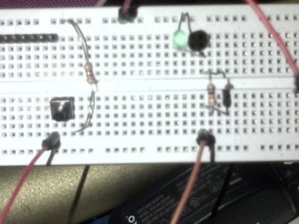
See the video below of my servo working! It doesn’t seem to be spinning the full 180 degrees, so I need to play with the numbers some more. Maybe I’m not giving it enough time to move all the way.
My dad zoomed in real close on the servo because he didn’t want you to see how bad the soldering was on the batteries. He’s terrible at soldering! But don’t tell him I said that.
Controlling GPIO with Scratch 🙂
Today I was continuing with Scratch but it was a little-bit different. I was trying to control GPIO pins and my breadboard using Scratch. This type of Scratch was absolutely full of interesting new ideas, possible projects and other worlds of wonder! If you can control gpio pins, you can do anything! (insert mad scientist laugh here)
The instructions that I followed are found here but they’re a little complicated for a noob like me. So, I had to look at other pages also to read resistor color codes, find pin diagrams, and use variables in Scratch.
The first step is to install a new version of scratch that has support for GPIO. Here are the commands. It’s best to copy and paste them because there are many opportunities to make typing mistakes (this all goes on one line):
sudo wget https://dl.dropbox.com/s/gery97qildl7ozd/install_scratch_gpio.sh -O /boot/install_scratch_gpio.sh
then
sudo /boot/install_scratch_gpio.sh
When you type “startx” and go into Linux, you’ll notice a new version of Scratch (don’t worry, your old version is still there too). You’ll see some new things. There’s a block called “broadcast” that will let you turn on a GPIO pin by putting “broadcast pin11high” for example.
So, first, I connected an LED (and resistor) and ran the program that comes with it to blink the LED. It was pretty simple, turn pin 11 high for one second and then low for 2 seconds. But I decided that I wanted to use a push button on the breadboard. The website above talks about inputs a little bit, but I had to go to other pages to figure out how to wire it up. This one worked for me.
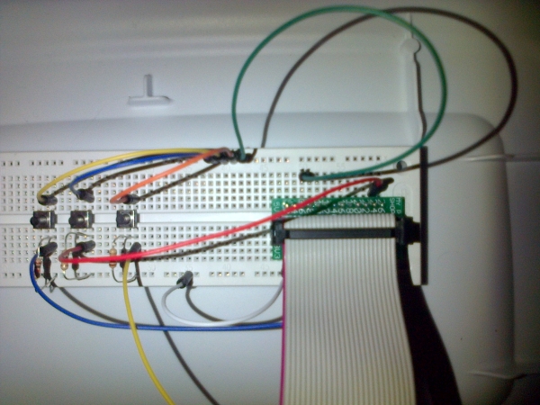 To figure out if the button is pressed or not, you use a “sensor value” block. I used pin7, so my block said “pin7 sensor value”. I wanted to put this into an “if” block, but it wouldn’t let me. So, I put it in a “think” block and I could see that when the button was not pressed, Scratchy would think “1” and when it was pressed, Scratchy would think “0”. So, I ended up storing the 1 or 0 in a variable called “button” and I used an “if” statement, “if button = 0” to trigger the program when the button is pressed.
Only problem with my little program is that I have to hold the button down. I might try to make it so that I press it once to start the blinking and again to stop the blinking.
I earlier read about someone who controlled a RC car with the Scratch Programming language and an RPI. I feel that that is really cool and hope that I could do something like that but with my own nerdy, girly flare to it. Now that I am able to control LEDS…… I CAN CONTROL THE WORLD mwa ha ha, just kidding.
For mroe detail: Servo Motor with Raspberry Pi and PWM