
Story
In this sample, we’ll connect an 8-bit serial-in, parallel-out shift register to your Raspberry Pi 2 and create a simple app that uses the shift register to control eight LEDs.
This is a headed sample, so please ensure that your device is in headed mode by running this command: setbootoption.exe headed (changing the headed/headless state will require a reboot).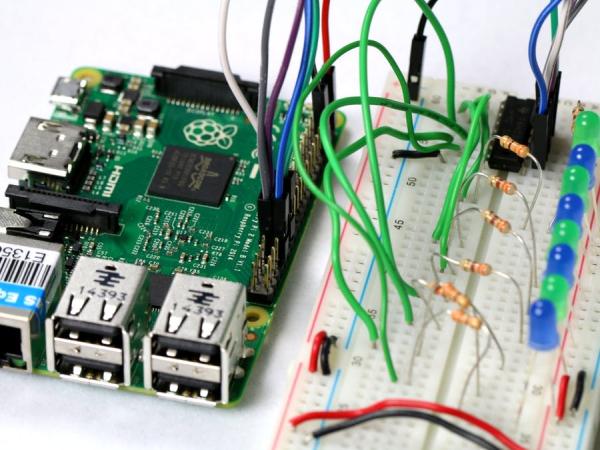
Connect the Shift Register to Your Device
You will need the following components :
- 1 Raspberry Pi 2
- 1 74HC595N serial-in, parallel-out Shift Register
- 4 blue LEDs
- 4 green LEDs
- 8 330 Ω resistors
- An HDMI monitor
- A breadboard and several male-to-female and male-to-male connector wires
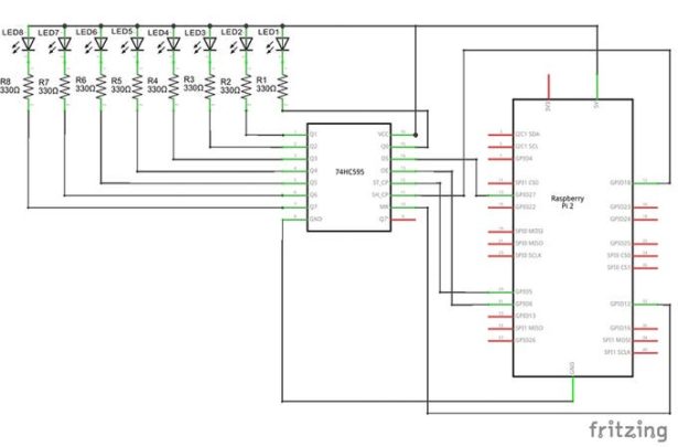
Let’s start by wiring up the components on the breadboard as shown in the diagram below.
Note: Make sure to power off the RPi2 when connecting your circuit. This is good practice to reduce the chance of an accidental short circuit during construction.
Connecting the 74HC595N Shift Register
Place the Shift Register on your breadboard such that it straddles the center gap of the breadboard.
Locate pin 1 of the 74HC595N shift register by finding the notch on the IC. If you orient the IC so that the end with the notch is facing left, pin 1 will be the first pin in the lower left below the notch.
Make the following connections on the 74HC595N shift register:
- Pins 1, 2, 3, 4, 5, 6, 7 and Pin 15 Q0 thru Q7: Connect each of these pins to a 330 Ω resistor – one 330 Ω resistor for each pin
- Pin 8 GND: Connect to the ground rail on the side of the breadboard (blue stripe)
- Pin 9 Q7’: Leave unconnected
- Pin 10 SRCLR: Connect to GPIO 12 (pin 32) on the RPi2 (pin mapping is below)
- Pin 11 SRCLK: Connect to GPIO 18 (pin 12) on the RPi2
- Pin 12 RCLK: Connect to GPIO 5 (pin 29) on the RPi2
- Pin 13 OE: Connect to GPIO 6 (pin 31) on the RPi2
- Pin 14 SER: Connect to GPIO 27 (pin 13) on the RPi2
- Pin 15 Q7: See above.
- Pin 16 VCC: Connect to the voltage supply rail on the side of the breadboard (red stripe)
For more detail: Shift Register Sample