
I needed to control a DC motor from my Raspberry Pi’s GPIO port as part of my time-lapse dolly project. I had to be able to turn the motor on for approximately 150ms which would in turn move the dolly along by 3mm.
Parts
- 12VDC Mini High Torque Motor – Max 50mA at full load – Buy on Amazon
- PN2222 NPN Transistor – Buy on Amazon
- 270Ω Resistor – Buy on Amazon
- 10kΩ Resistor – Buy on Amazon
- 1N4003 Diode – Buy on Amazon
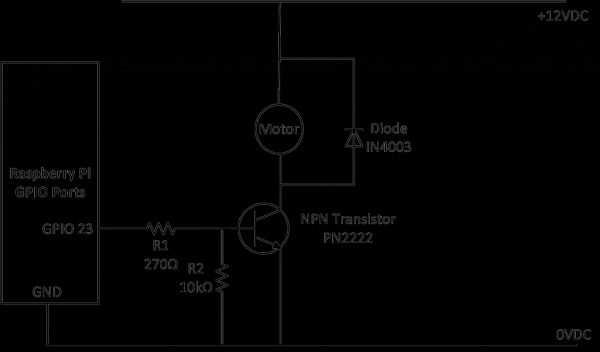
Circuit Diagram
- The NPN transistor acts as a switch. It allows current to flow from the collector to emitter when a potential difference is applied the across base and emitter. See Wikipedia for more info on how they work.
- The 270Ω resistor (R1) protects the Raspberry Pi’s GPIO port by ensuring that not too much current flows from the GPIO port.
- The 10kΩ resistor (R2) helps pull the base back down in case there is some leakage. You may not require this one but add it if you see the motor turning very slowly.
- The diode ensures that reverse current generated by the collapsing of the DC motor’s field when the motor is turned off does not damage the NPN transistor and GPIO port. Diodes only allow current to flow in one direction.
- The 12VDC motor in this circuit draws up to a maximum of 50mA under full load. To check the max load of your motor connect an ammeter in series with the motor to a battery and hold the shaft and watch where the current maxes out.
For more detail: Simple way to control 12V DC Motor using Raspberry Pi’s GPIO port and NPN transistor