
Introduction
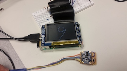
Nowadays, in order to gain the handwriting results, people often rely on the capacitive touch screen, stylus pen, or other similar devices. They are functional and precise, but not always flexible. Our project combines Raspberry Pi with IMU to build a product that can keep tracking of the movement and generate the trajectory very quickly. We designed a system that does not need any specific surface or other input tools for support and it only reply on IMU and its sensors. By connecting IMU with Raspberry Pi, when IMU device moves, the sensor data will be transmitted from IMU to Raspberry Pi. Then using our program and algorithm, restore the IMU movement. The movement will be recorded and stored in Raspberry Pi. With PyGame, the movement also can be displayed on TFT screen of Raspberry Pi. With a small and convenient button, the recording function can start and finish very flexibly. Users also can attach our device on other things to track their movements, too. Therefore, our device provides a workable solution for handwriting tracking, movement tracking and etc.
Objective
The goal of the project is to design a separate module that can be put on a pen, robot or even people to track and record the object movement. Users can use this module and attach it with their other devices, so when the object is moved, our device can restore and track their trajectory and display the movement in the horizontal plane in the world frame on the screen. A very classic application is that users can use it as a pen, so their writings will be recorded and saved as an image. A special feature about this project is that the tracking does not reply on any specific plane and it can be applied on every plane, even in the air. The placement or tilt of the device also will not affect the final result.
We use Raspberry Pi and Inertial Measurement Unit to be the main components for our project. Also, PyGame is used to display the trajectory on Raspberry Pi.
IMU Calibration
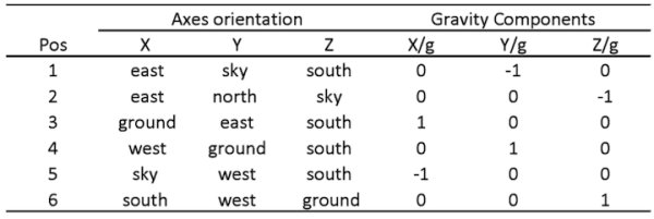
Due to fabrication inaccuracy, the 3 axes of the accelerometers and the 3 axes gyroscopes are usually misaligned, causing an error between the Euler Angle of two coordinates. Calibration is needed. Using the 6-pos calibration technique, we setup the 6 calibration position as follows:
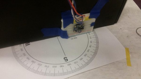
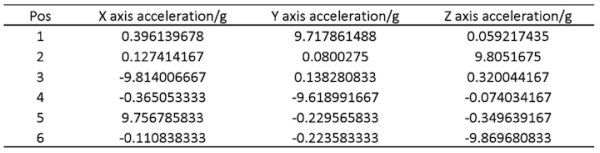
Using a self-made calibration table (Figure XX) we fix the imu to the 6 positions and record the reading, the calibration data gathered by these six positions are:
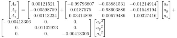
The acceleration data after calibration is (Ax, Ay, Az are data after calibration and ax, ay, az are raw data):
Sensor Fusion For Raw Data
Quaternion calculation:
Quaternion is a representation of the orientation and rotation of the object, and it is easier to compute the rotation of vector than the Euler Angles. The transaction between the quaternion and the Euler Angle is shown below:
Quaternion rotation:
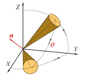
For a fixed vector V coordinated in frame XYZ, it could be represented in quaternion:
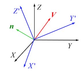
If the frame rotates for q, become X’Y’Z’, V coordinated in X’Y’Z’ could be represented as:
Then,
However, using the raw data generated by the gyroscope is still not enough, because of the misalignment mentioned in calibration part, the gravity vector obtained by the accelerometer need to be considered. The function ‘UpdateIMU’ is used to calculate the error between the gravity vector calculated by gyroscope and the gravity vector measured by the accelerometer. This function was run 2000 times at the beginning stationary stage with no movements nor rotations, and using a feedback to calculate the error. The function is shown below:
1 2 3 4 5 6 7 8 9 |
 def UpdateIMU(self, Gyr, Acc):
        if np.linalg.norm(Acc) == 0:
            warnings.warn("Accelerometer magnitude is zero.  Algorithm update aborted.")
            return
        else:
            Acc = np.array(Acc / np.linalg.norm(Acc))
        v = np.array([[2*(self.q[1]*self.q[3] - self.q[0]*self.q[2])],
                [2*(self.q[0]*self.q[1] + self.q[2]*self.q[3])],
                [self.q[0]**2 - self.q[1]**2 - self.q[2]**2 + self.q[3]**2]])
|
Variable “Acc” and ‘v’ are both normalized gravity vector calculated by the accelerometer and the gyroscope, then the angular deviation (error) between the two vector could be represented using their cross product:
1 |
error = np.cross(v,np.transpose([Acc]),axis = 0) |
The calculated error could also be integrated to update the gyroscope reading using PI negative feedback loop (that’s why we need to run this function 2000 times, so the PI loop could converge):
1 2 |
self.IntError = self.IntError + error Ref = Gyr - np.transpose(self.Kp*error+self.Ki*self.IntError) |
The quaternion could then be calculated by the corrected gyroscope data:
1 2 3 4 |
pDot = np.multiply(0.5 , self.quaternProd_single(self.q, [0, Ref[0,0], Ref[0,1], Ref[0,2]])) self.q = self.q + pDot * self.SamplePeriod; self.q = self.q / np.linalg.norm(self.q); self.Quaternion = self.quaternConj(self.q); |
Read more: Smart Pen: Final Project for ECE5725