
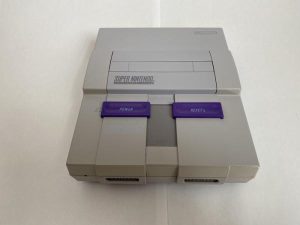
This project is for transforming a non-functional SNES into a retro-emulation powerhouse using a Raspberry Pi.
As with most people during 2020, I began to rediscover old video games that I either loved to play or never got a chance to finish. I'm a Nintendo fanboy at that, and in 2020 I came to the unsettling realization that I had never owned a Super Nintendo. With the rising price of retro video games and consoles, I thought it might be fiscally irresponsible to attempt to build out a full library of games on a new (to me) console. I was, however, able to purchase a SNES that met its unfortunate fate after a spilled soft drink fried its motherboard (according to the eBay seller).
There are several other great Instructables on this same concept, and much of my inspiration comes from their projects.
SNES RetroPie System by severdhed
Turn a Super NES Into a Universal Game Player by vigothecarpathian
Ultimately, I wanted to make this project as non-destructive to the original console parts as well as maintain as much original functionality as possible.
Supplies

There are a couple methods you can take with this.
At a bare minimum, you will need:
- A Super Nintendo console
- Gamebit Screwdriver (Larger size is needed for this project. Smaller size is for cartridges.)
- Raspberry Pi (I used a model 3 B+)
- Micro SD Card (to run the operating system and store ROMs)
- USB to Micro USB Cable (to power the Raspberry Pi)
- Momentary Pushbutton Switch with 2-pin connectors
- Hot Glue Gun and Glue Sticks
- Solder wire (for electronics)
- Soldering Iron
- Wire Strippers
- Heat Shrink Tubing (you could just use electrical tape instead, but heat shrink tubing looks better and is more secure)
- Nylon Standoffs for Raspberry Pi
Optional Equipment:
- 3D Printed Rear Panel Replacement (can be skipped if you don't have access to a 3D printer – alternative steps will be included later)
- 5V Power Adapter and USB Adapter*
- HDMI Female-to-Female Mount*
- Thin/Flexible HDMI Cable*
- 3D Printed Rear Panel
*if using the 3D printed rear panel
Step 1: Empty the SNES
![]()
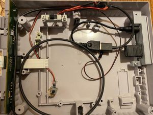
Using the Gamebit screwdriver, remove the 6 screws on the bottom of the SNES to open the console. On the inside, you will need to remove the “eject” lever by lifting the bar on one side to slide it out the other side. There will be several phillips-head screws holding the stock motherboard in and the shielding. You will not need any of these parts, but I held on to mine just in case I one day decided to see if I can fix it. (Note: in the third photo, I had already installed the reset/safe shutdown switch. I forgot to take a photo before that)
DISCLAIMER:
PLEASE do not do this project on a working SNES. There is no need to destroy a working console for this project, and as they get older and more fragile there are becoming less available to people who will actually use them and preserve them. I had my SNES motherboard confirmed to have been damaged beyond reasonable repair.
Step 2: Install the Safe Shutdown Button
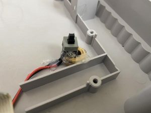
In order to make use of the buttons on top, and safe usage of the Raspberry Pi, I thought it would be good to use the “reset” button as a trigger for a safe shutdown script on the Pi.
I used a threaded nut as a spacer on the bottom portion of the shell with the center point secured by hot glue 6.5 mm from the front of the console and 5.5 mm from the right side (looking at the front of the console). The nut was 1 cm tall, and I mounted the pushbutton switch on top of that as centered as possible. This layout will push the button in the same way as the original console reset button did without any modification to the top shell or the reset button mechanism.
In order to set up the script on the Raspberry Pi, I followed this guide that walks through the process step-by-step and provides a simple download for the script:
https://howchoo.com/g/mwnlytk3zmm/how-to-add-a-power-button-to-your-raspberry-pi
It's important to make a note of which GPIO pins you will use for the script, but it's not advised to leave it in at this point of the build as we will need to do more work before securing the Raspberry Pi.
Step 3: Wire Up the Power Button
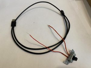
For this part, I used the stock power switch to tap into a USB to Micro USB cable and function as the power switch to the Pi itself. For this, I secured the wire in my Helping Hands soldering station and made an incision with an X-Acto knife through the insulation and the shielding to expose the RED wire that provides power through the cable. After maneuvering it out of the main part of the cable, I cut it in half with my wire cutters and stripped portions of it to expose the core. After preparing some putting heat-shrink tubing on the wires, I secured it with solder and sealed with the heat-shrink tubing.
If you don't plan on using a 3D printed rear-panel or a power adapter, this part can be skipped but I feel it's important to keep the console functioning as it was intended.
Step 4: Secure Ports to Rear Panel (if 3D Printing)
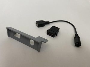
For this step, I used this model from Thingiverse and modified it slightly to fit my AC adapter to USB part. The AC adapter is friction-fit, and the HDMI adapter is screwed in with small screw holes and provided screws. I also secured with a small bead of super glue to ensure pieces won't slide out when connecting or disconnecting cables.
Step 5: Secure Raspberry Pi (if Not Using 3D Printed Part)
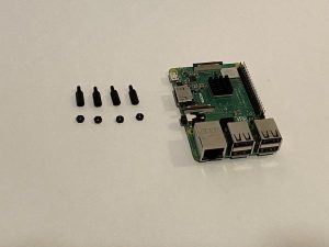
For this part, I recommend using nylon standoffs to elevate the Raspberry Pi board a bit. Secure them to the bottom of the Pi and place it in front of the opening where the rear panel used to be. I would recommend using small beads of hot glue on the standoffs to secure it to the bottom shell. This way, the power and HDMI ports will be open and accessible.
Step 6: Assemble
Install RetroPie to your Micro SD card before assembling. I used the guide on the RetroPie website:
https://retropie.org.uk/docs/First-Installation/
Once you have all of the parts inside the bottom shell that you're using, arrange it all inside and make sure that the top shell can still close securely and the eject button will fully depress. I wish I could say there's a good method to this, but unless you use the exact same materials that I did, it will likely be a bit different from person to person. My Raspberry Pi isn't secured inside but the arrangement of the cables does hold it in place well and I don't plan on shaking my SNES too much so I'm not worried.
Using the Gamebit screwdriver just as you did when you opened the shell, replace the screws and close it.
Step 7: Plug in and Enjoy!
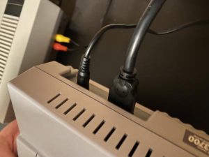
Once everything is secured, you're ready to play! Enjoy the classics in HD or install some shaders and scanlines for a more authentic experience!
For controllers, I found these Wireless USB SNES Controllers that were very affordable. Before closing up the console, I plugged the dongles into the USB ports on the Raspberry Pi so I wouldn't have to worry about connecting or disconnecting the controllers. If you have bluetooth controllers for a system such as Playstation or Xbox, you can connect them to the Raspberry Pi and use them as-is.
Step 8: Final Thoughts and Some Considerations
If you'd like to be more old-school and use wired controllers, this Pi SNES project replaces the standard front controller ports with USB ports where you can plug in modern USB SNES controllers.
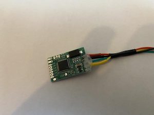
If you want to be really old-school, you can use an SNES controller to USB modification like severdhed did with their project or solder a new adapter into the original front ports using the SNES to USB chip from Raphnet. This is a modification that I may include in the future, among others I thought of while I was working on this. I had every intention of incorporating this, but I wasn't confident enough in my soldering skills and I felt I should elicit some assistance from someone more experienced in electronics soldering. This is a very small chip that was shipped from Japan and I really don't want to have to order another one!