
Authors:
-
Alexandru Radovici, Ioana Culic, Maria Tudor – Wyliodrin
-
Bogdan Doinea – Cisco Networking Academy
This document describes how to build a Social Alarm Clock by a team of five people: a manager, a product designer, two engineers and a programmer.
Introduction
We are going to make a smart wake up lamp. You should already be grouped in teams of five. If you are more than 5, feel free to assign a technical role to multiple people and work together. Each member of the team will have a different role, so please assign the following roles to each other: 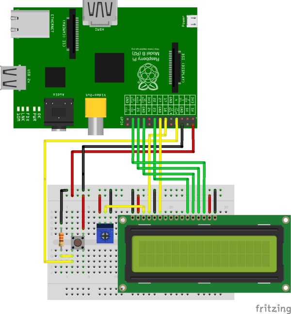 Manager – ensures the projects are implemented and that everybody is working. Also keeps in touch with the Technical Managers.
-
Designer – uses Lego blocks to design and construct the box
-
Programmer – programs the software inside the boards
-
Two Engineers – connect the Raspberry Pi and the Arduino, the peripherals of I/O, connect the wires
Please complete the following table with the names of the team members and their roles.
| Name | Role |
|---|---|
| Manager | |
| Designer | |
| Engineer | |
| Engineer | |
| Programmer |
Wyliodrin Setup
Wyliodrin Accounts
All tea m members with a computer are required to sign up for a Wyliodrin account. Please go to http://www.wyliodrin.com.
Raspberry Pi and Arduino Setup
Board Setup
Sign in with your Wyliodrin account. After signing in, you will find on the top of the projects page a button with Add new board. Please press the button to add the Raspberry Pi to your account. To add the board you have to complete these two steps:
-
name the board and select the type
-
set up the network connection
SD Card Setup
Additional Information
Project 0 – Play a radio Station
Connect the speaker
Performed by: Engineers In your kit you will find an X-Mini Speaker. The speaker has two cables:
-
a jack for audio located underneath
-
a mini USB cable for power, the speaker has a battery, just to make sure, please connect the mini USB cable to the speaker and plug it in the computer so that the battery gets charged
Connect the jack cable to the jack output of the Raspberry Pi.
Start a radio station
Performed by: Programmer On the projects page, you have a button Create new application. Press the button. You will be asked to name your application and select the language. Name it Speaker and select the language Music – Visual Programming. This will create an application starting from an example for playing music.
Look at the project
Project 1 – Build the case
Phase 1 – Design the case
Performed by: All team members
Think of a suitable design for the case so that the plastic board with the Raspberry Pi and the Arduino on top, can fit in. The box should be five layers high. Please do not forget to leave spaces for the Ethernet, power and jack cables. Look at the breadboard with the LCD and find a way to anchor it in the box. Place the speaker next to the wake up lamp.
Phase 2 – Build the case
Performed by: Designer You will need:
-
the LEGO bricks box
-
the LEGO plate
-
two screws
-
a screwdriver
-
the plastic board for the Raspberry Pi and the Arduino (RedBoard)
-
tracing paper
Build the case you designed in the previous phase. Please open the LEGO bricks box and place all the LEGO bricks inside the plastic box. This way you will have them in hand. Fix the Arduino on the plastic board using the two screws available in the Lab Pack. Insert the red USB cable into the Arduino. Right next to the Arduino you will place the Raspberry Pi.
Place the board on the LEGO plate and build a box around it. We recommend starting with the small blocks as you will need the long blocks in order to anchor the LCD. Put the paper upon the box and tie it with tape.
Project 2 – Light up a multicolor LED
You will need:
-
a Raspberry Pi connected to Wyliodrin
-
An Arduino (RedBoard)
-
an RGB LED
-
three 330 Ohm resistors
-
three female-female jumper wires
-
four male-female jumper wires
Connect the Arduino and the LED
Performed by: Engineers Connect the Arduino to the Raspberry Pi through the red USB cable. Connect the RGB LED to the Arduino following the schematics below. The RGB LED has four legs: red, ground, green, blue. The longer leg is the ground, it will be connected with a male-female wire to the Arduino pin named GND. The other pins will be connected to pins 9, 10, 11 via 330 Ohm resistors. 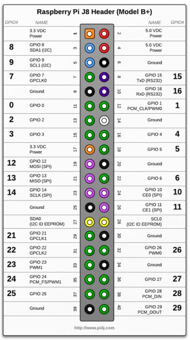
Light up the LED
Performed by: Programmer Go to the Wyliodrin Applications page and create a new application. After you name it, select the language New – Visual programming. Press Next. On the second page, select Connect an Arduino to the board (Raspberry Pi only). This will add an Arduino component to your application.
Project 3 – Write CISCO on the LCD
You will need:
-
a Raspberry Pi connected to Wyliodrin
-
a 16×2 LCD from the Lab Pack
-
a breadboard from the Lab Pack
-
8 male-male jumper wires
-
8 male-female jumper wires
-
a rotary-angle
Connect the LCD
Performed by: Engineers Place the LCD on the breadboard and connect it to the Raspberry Pi as shown in the picture.
For more detail: Social Alarm Clock