
As my projects evolved in my mind there comes a time to make the ideas come true and so the project below became reality. Its an Arduino based soil moisture sensor, with 16,×2 LCD, real time clock (which keeps time even if the power supply is disconnected), temperature sensor and SD data logger.
It can be very helpful with a bachelor's degree or master's degree biotechnology/biology/botanics/plant keeping projects.
The idea of the project is to build a moisture sensor, both portable and stationary (with 9V battery or supplied with a standard adjustable charger). Its going to take very short measurments every X miliseconds, depending from how you will set it. Why the measurments need to be short? Becouse there is a problem which need to be solved and got solved in an article:
http://www.instructables.com/id/Have-a-Bumper-Crop… —– By: Robert M / ArduinomasteR
who improved my first instructable which im very grateful for:
http://www.instructables.com/id/Arduino-LCD-Soil-M… —– By: Wojciech Marczak / WojciechM3
Those two articles became the base for my idea, how to improve it and make it even better
So the idea to make the probes last longer is to let the current only flow in a short time (2x 30 miliseconds in our case) and to turn it off for a set amount of time, for example 1,800,000 milisecounds = (30x60x1000) = 30 minutes. To set this value you need to change the delay at the very end of a project.ino file.
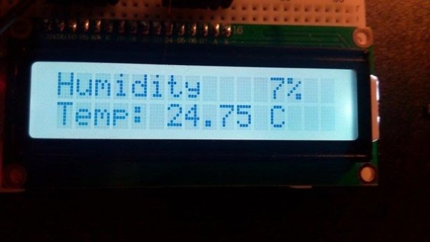
However, since we have the sensor which takes the measurements every X miliseconds, now we need map the values. The values will vary from 1000 and something about stable 400, However the lower the measurment the lesser is the resistance, and since the probes check the resistance between two bolts we need to make Value of 400 or similar to be humidity 100% and a bigger resistance, 1000 or above means the humidity is 0% So we need to map the values of 1000 –> 400 to be humidity 0 —> 100%
All of those things will be done in the next steps of this instructable.
Step 1: Gathering Parts
Picture of Gathering Parts
You will need:
– Arduino Uno (for example)
– Real-Time Clock (RTC) DS3231 with battery
– MicroSD + SD adapter / SD Card
– SD Module
– 16×2 LCD
– YL-69 Soil moisture sensor
– Wires
– Potentiometer, i useed 47k , but thats only because i couldnt find any 10-20k Ohm potentiometer in my parts collection
– Breadboard
You can buy all of these really cheaps, since all of those are made in china as a mass production.
Step 2: Connect the parts
Picture of Connect the parts
Now you need to connect the parts, as its shown on the picture. However every SD Card Module is a bit different, every LCD is different and every RTC is different, you need to check the manufacturer papers to be sure that you're connecting all of the cables in the correct way.
LCD:
In my sitiation, the proper way of connection is shown on the schematic and a picture (there are the name of pin outputs).
The proper way of connection in my case is:
(1) VSS < ———————— > Ground, GND rail on the prototype board
(2) VDD < ———————— > +5V rail on the prototype board
(3) V0 < ———————— > To potentiometer middle leg (regulated output)
(4)RS < ———————— >Pin 10 on Arduino board
(5) RW < ———————— > Ground, GND rail on the prototype board
(6) E < ———————— > Pin 9 on Arduino board
(7) D0 < ———————— > NOT CONNECTED
(8) D1 < ———————— > NOT CONNECTED
(9) D2 < ———————— > NOT CONNECTED
(10) D3 < ———————— >NOT CONNECTED
(11) D4 < ———————— > Pin 7 on Arduino board
(12) D5 < ———————— > Pin 6 on Arduino board
(13) D6 < ———————— > Pin 5 on Arduino board
(14) D7< ———————— > Pin 3 on Arduino board
(15) A < ———————— > +5V rail on the prototype board
(16) K < ———————— > Ground, GND rail on the prototype board
SD Card Logger:
The schematic of connection:
GND < ———————— > Ground, GND rail on the prototype board
+5V < ———————— > +5V rail on the prototype board
CS < ———————— > Pin 4 on Arduino board
MOSI < ———————— > Pin 11 on Arduino board
SCK < ———————— > Pin 13 on Arduino board
MISO < ———————— > Pin 12 on Arduino board
YL-69 board:
We are only going to use 3 pins:
– VCC < ———————— > Pin 2 on Arduino board
– GND < ———————— > Ground rail on the prototype board line
– A0 < ———————— > Analog Pin A0
We are not going to use D0, its a digital output, there is no need to us to use it in this project and we… won't use it.
RTC DS 3231 + battery
Battery is needed to keep time when the main power source is disconnected. The pins we will use are:
– SCL < ———————— > SCL (on Arduino board)
– SDA < ———————— > SCA (on Arduino board)
– VCC < ———————— > +5V rail on the prototype board line
– GND < ———————— > Ground, GND rail on the prototype board
Potentiometer
Its use to set the proper current value to adjust the LCD display. If there is no letters show on the LCD and you're sure they should, manipulate the potentiometer and it will appear if its connected properly.
Step 3: Set the time
Picture of Set the time
When you use your RTC for the first time you need to set it up. You won't need it later, but the first setup is needed and crutial. To set the time you're going to need Sodaq DS3231 library.
You can get it thru “add library” option in arduino program. Just click add library and type “3231” And you ll have it shown. You need to install it now.
However:
If there is no Sodaq DS3231 library to install use this link to GitHub:
https://github.com/SodaqMoja/Sodaq_DS3231
Load the sketch “adjust” and change those values:
DateTime dt(2011, 11, 10, 15, 18, 0, 5);
in that order:
“year, month, date, hour, min, sec and week-day(starts from 0 and goes to 6)”
with the correct ones.
You only need to do it once. If thats done, the time is set.
Step 4: Code
If everthing is connected you need the code! And thats why i prepared a file with the sketch and a HUGE amount of comments about what are we doing in the different sections. I also decided to take the measurements of the temperature, since an DS3231 have also an abbility to measure the temperature, so it would be a waste not to use it, when we can also dump it into SD card.
Standard Project version is made to cooperate with serial monitor and SD card, which means it wont work without serial monitor connected. Its not the greatest idea, when you want your device to be portable, thats why i made another sketch, which doesnt require serial monitor to be opened and doesn't use it for anything. That makes the code simplier, so thats also nice. Portable.rar includes the code for a portable version, which doesnt use Serial Port, as it's not needed in portable version.
Important part of the code are the lines which effects with 3 letters in the right-bottom part of the screen. Those letters are :
– “I” from “initialized”, indicates that the SD card is present
– “E” from “Error”, indicates that the card is NOT present
– “F” from “False”, indicates that the file is NOT available, but the card is present.
Those 3 letters are written, to help you diagnose the problem if it occures.
You also need the proper power supply, and the choice depends from the future use of your device.
You can use:
– Standard adjustable charger
– 9V battery with the connection wires.
The choice of your power supply is a very important point of the project, if you plan it to be a stationary device much better decision would be to use adjustable charger. However if you want it portable, the battery is your only choice. However there is also another trick to be used with the portable devices, also given to us by:
http://www.instructables.com/id/Have-a-Bumper-Crop… —– By: Robert M / Arduinomaster
The trick is to dim the LCD if its not needed, you can check our his short code to get howto dim the screen. I didnt use it, because i decided thats not necessary for my project, however that might be a next point of interest in makeing the device work better in the portable version. For my Master's thesis i need it stationary, and thats how i build it. However its important to note, that it CAN be portable.
Step 6: SD Cards selection
Picture of SD Cards selection
I found out that some of the SD cards dont want to work properly with my model of SD Card module.
From the expirience i can answer for at least two questions.
1. Do all of them work? No, they dont. Some cards just dont want to cooperate with us. I found out that the ones which dont want to cooperate are SDHC. Normal SD cards (also microSD in SD standard) works just fine, but that might be true just for my cards. Some of the cards work good, other cards dont work at all or work, but you can't save anything on them and the data crush everytime you attempt to unplug the SD card from the SD module.
2. Is there any difference if its SD card or a microSD + adapter? No. As far as my expirience shows there is completly no difference. Both work for me. However, as my favorite teacher says:
“However you can't always belive in lifetime expirience, because a lifetime expirience show us that always someone else who dies. And we know that is only partly true, because there will be our day one day” S. Michalkiewicz
And with that positive accent i would like to end This instructable. Once again big thanks to Arduinomaster for an oppurtunity for a cooperation.
Build it, use it!:)
Step 7: Continue!
I'm going to continue the work as my project is still evolving, there is still a PCB and a wooden box needed, stay tuned!
Step 8: PCB | EXPERIMENTAL, NOT FINISHED YET (MIGHT NOT WORK!)
Picture of PCB | EXPERIMENTAL, NOT FINISHED YET (MIGHT NOT WORK!)
I also decided that it needs a PCB to connect everything with minimal use of wires. I decides so because i have a lot of PCB's and only a few wires. And there is no sense in buying a new breadboard and wires, when i can make a PCB. Unfortunately for me, but good for you is that i have only single sided PCB's, so we have to use some wires connected from the bottom of my PCB.
This are the projects of the PCB, As a ,fzz (Fritzing project file), Exported as PDF in PCB.rar in different layers, normal one with and without marked connections (needed because of that the PCB i have is only single sided) and a black on white to print that on
For More Details: Soil Moisture Sensor with SD logging