
1. Introduction
Ever since I started playing the violin when I was three years old, both listening to and playing music as been one of my strongest passions. The study of music theory is something that I have pursued since senior year of high school, but even after years of study and practice tasks such as musical analysis and transcription, which allow for musicians to more deeply appreciate other artists' compositions still prove to be tedious and time consuming tasks. Both of these tasks require the knowledge of what chords are underlying in the piece. One of my favorite activities to do is get together with a group of my friends and make music through improvisation; knowing the chords that are being played makes the process of improvising with other people exponentially easier. The creation of a stand-alone device that performs chord detection from an auditory input would act as a very useful tool, for not only myself, but also other musicians. The heart of the motivation for this project is to create a useful tool for musicians which can be used by anyone, anywhere. Essentially creating a device that is small enough to fit in a musician's instrument case that is able to perform chord recognition.
The following report will outline the background research, the design requirements, the design alternatives, the initial proposed design, the final implementation, as well as the results and conclusions that came about from this project.
2. Background
The music industry is one that has been booming for the last century. From everything from the manufacturing of instruments and equipment to marketing of albums and concerts of artists. Although making a career in the industry is hard, much of the marketable aspects of the music industry are for those who enjoy playing and listening to music as a hobby. This is because music is something that has been integrated into the everyday modern life, whether it be directly or indirectly for example through a TV-show, website, or even standing on an elevator.
Instrument tuners such as tuning forks have existed throughout history almost as long as written music itself has existed. In the mid 1900s an electric tuner was invented which became a useful tool for musicians everywhere.[1] Instrument tuners today are devices that the many musicians rely on and carry with them because they are devices which are portable and allow for instruments to be tuned in a matter of minutes without having to rely on ones hearing. Currently, there are a plethora of softwares that are able to perform chord recognition (both open-source and proprietary), that use a various different algorithms to achieve the end goal. There are also various softwares that exist that are able to perform more advanced operations on music signals such as key detection and automatic transcription. Currently however, there is no device that is stand-alone and is able to perform any of these operations on musical signals. The creation of such a device would not only be a great tool but would also be very marketable from a musicians stand-point.
Music theory is a subject that focuses on studying and analyzing the components that music is comprised of such as sound, pitch, melody, harmony, rhythm, form, and notation. This subject is not only studied by musicians,but also by people who are interested in further appreciating and understanding musical compositions. At the heart of the project, is an idea of creating a device that is instilled with enough music theoretical knowledge in order to perform useful calculations and operations. The most basic component is that of a note. In the western tonal music system there are 12
different notes that span across many different octaves. For this project a note will be considered as a mapping of frequencies to various letter names and octaves. When certain combinations of notes are joined together they are able to build more complicated musical components such as scales, chords, and keys; all of these structures can be looked at from a technical standpoint as being varying harmonic structures.
One of the ways that a musical signal can be processed by a computer is using symbolic data type such as MIDI (Musical Instrument Digital Interface) format. The data can either be inputed as an acoustic signal and then transferred into symbolic data or directly input as symbolic data. Using symbolic data contains the advantage that more information about the signal such as velocity and pitch, in the form of on/off messages can be stored. Key recognition using symbolic data has proven to be extremely accurate.[4, 6]
When analyzing an acoustic signal, one of the most useful ways of approaching the problem is by using Digital Signal Processing. By using Digital Signal Processing, various filters and transforms can be applied to the signal in order to manipulate the original signal into something more useful. One of the most useful tools is using the Fourier Transform. When the Fourier Transform is applied to a signal, the signal is transferred from being a function of time and amplitude to being a function of frequency and amplitude. This is useful because after the Fourier Transform has been computed, it is much easier to extract information about various frequencies and therefore notes, that are contained within the signal that would have otherwise been impossible to extract from a signal in the time domain.
When musical signals are processed by a computer to perform these operations without using a symbolic data representation, it often incorporates the use of Pitch-Class Sets or Pitch-Class Profiles.[2, 3, 5, 7, 8, 9] A Pitch-Class Set is a way of extracting individual note information from the signal using frequency analysis, creating a set that is representative of the signal but in terms of the various notes in
the 12-tone western music system. A Pitch-Class Profile is essentially a database made up of many Pitch-Class Sets. The Pitch-Class Profile is comprised of various chords or keys depending on if chord recognition or key recognition is trying to be accomplished. This idea is often used explicitly but can has also been used implicitly. One way of searching through Pitch-Class Sets is by using a pattern matching algorithm.[3, 8] Another technique that has proven to be effective is by using Hidden Markov Models. A Markov Model is a probabilistic reasoning tool made up of a series of states and transitions, where each transition is weighted based on the probability of that transition occurring and each possible future state is only dependent on the current state being looked at. A Hidden Markov Model is an extension of a Markov Model, taking the same structure of a Markov Model except that for state, only part of the current state is known. This is most useful when multiple chords are being predicted over a long period of time so that chord transitions can be predicted in order to help identify the tonality of a signal.[2, 5, 9]
3. Design Requirements
In order for this device to be able to be used as a useful tool for musicians, there are some essential requirements that must be met. The most basic of these requirements is the top-level definition of the device. The requirement for the input is that it should be a non-amplified acoustic signal. This means that the input to the device should come from either a microphone contained on the device or an auxiliary cable and should not be of a symbolic data type such as MIDI. Although applying chord detection algorithms to symbolic data is a much simpler task, it is not a very useful data type to be analyzing. Having an acoustic signal input also allows for any acoustic instrument to be able to be analyzed by the device as opposed to needing a specific instrument with a specific connection. The requirement for the output is that it must be displayed on a screen that is located on the device; the output that is to be displayed is not an intricate one so this will not be difficult to satisfy. Another fundamental requirement is that the device must be completely stand-alone. This means that this device should not simply be a program on a computer but rather should operate independently of what it is connected to, who is operating it, as well as the location of the device.
In accordance with how the device will take in and display data, the internal workings of the device must also have design requirements; the device must be accurate and operate quickly. These design criteria, unlike the previous ones are more difficult to quantify. It was determined that the device would be considered to be working reliably if it can identify the correct chord from the acoustic input at least 75% of the time. Although this may accuracy rate may not seem like a high enough one, when things such as chord ambiguity, noise, and mis-tunings are taken into consideration, it becomes a much more reasonable quantification of what accurate should mean for this project. The requirement for the time frame for how quickly the device must be able to detect a chord was chosen to be in between every one and two seconds; this can be considered to be a meaningful time rate for musicians. A very
typical speed for rock/pop music to be played at is 120bpm (beats per minute) and if it is taken into consideration that there are four beats per measure and that chords change on average between once and twice a measure than the requirement of chord needing to be detected between every one and two seconds can be deduced easily as one that will be useful for improvisation and .
So far, all of the design requirements that have been discussed have been directly related to the processes of the data acquisition that will occur on the device. There are a few other requirements that must be taken into consideration which apply directly to the underlying goal of making a tool for musicians. The first of these requirements is that the device must be user-friendly; the device not only must be able to be operated easily but it should also be able to be operated by virtually any musician without needing a background in Electrical or Computer Engineering. This should be able to accomplished easily by having the front end have a minimalistic design. The device must also be cost affordable, which has been chosen to be under $200 which will be able to be met by purchasing hardware accordingly. This requirement was chosen so that with the success of the creation of this device, it can be reproduced in a financially affordable manner.
4. Design Alternatives
For this project the most important component of the hardware is going to be the part that is responsible for the actual data acquisition on board the device. When choosing the hardware, there were a couple of key factors that had to be kept in mind. These factors were, how well they would be able to perform, how easily they would be to implement with other parts of the device, and how much they cost. Due to the fact that this project is very software intensive and there is no pre-written software for the project, it is important that the hardware that it is going to be implemented on is chosen carefully.
The first option that was considered was using a type of micro-controller called an Arduino. The Arduino proved to be very cost efficient, costing around 50$. Arduinos are programmed using C/C++ and an open-source IDE which would also be okay for this project because I have some experience with programming in C++. However, what the Arduino does not offer is any direct input for a microphone or auxiliary chord or a direct output for a display. This means that the addition of a microphone, audio jack, or digital display would not only require extra programming but would also require extra wiring; programming, wiring, and of course the debugging that comes along with these can be extremely time consuming. Although other types of micro-controllers could have been considered, Arduino seemed like the best option to consider because of its vast amount of libraries and support.
The next option that was considered was using an FPGA such as the DE2 Altera. I have had some experience with using this FPGA from the ECE-318: Digital Design course that I took last year which helped me way the decision in using an FPGA. If an FPGA were to be used it would most likely be programmed in VHDL or Verilog. These are two programming languages that I have a little experience with, but not a considerable amount. An FPGA would be great for doing many filter
calculations because of its extremely fast computing speed and I know from experience that the DE2 Altera has built in jacks for audio input as well as an audio core which can be accessed. However, the biggest setback with using an FPGA such as the DE2 Altera also comes from experience. I have previously tried to do a project involving the audio core on the DE2 altera, and it proved to be very difficult; I ran into many problems involving timing analysis as well as clocking issue when trying to use the audio core along side the video core, which would be responsible for the display. Creating a stand-alone device for chord detection is a project which is inherently much more complicated than the project I had previously attempted on an FPGA so it was decided that this would not be the best option either.
Another option that was considered was incorporating a Raspberry Pi as the base for the hardware portion of the device. The Raspberry Pi itself is a very diverse and adaptable device, so integrating a microphone and display into the device would be extremely easy since there is hardware that offers ‘plug and play' compatibility. The Raspberry Pi is also able to be programmed using many languages including Java, Python, C, C++, and Ruby. This would be useful because Python and Java are languages that offer many libraries and support for digital signal processing; I also have the most experience with these two programming languages. The Raspberry Pi is also very cost affordable, costing only $40 for the base component.
5. Preliminary Proposed Design
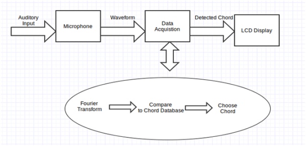
The device that is to be constructed consists of a hardware and a software component that will have to be integrated together. The design of the hardware component consisted of choosing what parts would need to be purchased in order to complete this project, where as the design of the software component consisted of designing an algorithm to do the data acquisition on the hardware and planning on how to integrate all of the hardware together. The following figure(Figure 1) shows a top-level diagram of the preliminary proposed design that is to be integrated.
5.1 Preliminary Hardware Design
The following table(Table 1) lists the hardware parts that were chosen for the preliminary proposed design in order to create this device; these are also the hardware components that were requested in the Student Research Grant Proposal Application.
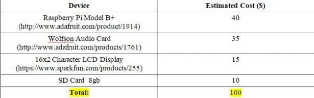
The Raspberry Pi B model was chosen as the base for the data acquisition system because it was deemed the most suitable for this project in accordance with the design requirements that have been outlined. The Wolfson Audio Card was chosen as an additive to the Raspberry Pi as an audio card component that will not only allow for better digital signal processing and sound manipulation to be done but also contains a higher quality audio input jack; this component was chosen in order to ensure that the input for the device would be able to be a non-amplified acoustic signal. The LCD display that was chosen is a very cost affordable and simple display that can easily be integrated with the Raspberry Pi. The output display that is to be shown on the device is simple and so it was determined that this display would be appropriate in accomplishing the output design requirement. The hardware will be driven by integrating the parts together and programming an algorithm controlling the data acquisition based on the proposed software design. This program will be stored on the 8gb SD card and is able to be loaded onto the Raspberry Pi from the SD card.
5.2 Preliminary Software Design
The software aspect of the preliminary proposed design encompasses an algorithm based on a couple of basic ideas. The first is the Fourier Transform, which is the heart of digital signal processing on auditory signals. The transform will be used to transfer the input data from the time domain into the
frequency domain which will allow for the amount of each individual frequency to be quantized and extracted from the original signal. This data will be able to be stored for comparison. Applying the Fourier Transform to a signal will also allow for various filters to be applied to the signal. The first step of the algorithm that is going to be incorporated is to apply the Fourier Transform to the input data, as well as a series of filters that will be used to reduce noise and highlight specific harmonic structures.
Another basic idea that was incorporated into the software design of this project was that of a Pitch Class Profile. A Pitch Class Profile is essentially a database that is created before the program is ran in real-time. This database or library will contain information about the harmonic structure of various chords. The various filters that will be applied to the input signal will allow for the the input signal to be compared to the library in order to try and match the input signal to a chord in the library. The matching progress will be done using probabilistic reasoning. Since no input signal will identically match anything that is contained in the library, a sensitivity will be created and the algorithm will try and detect which chord is in the input signal by finding which item in the library has the highest probability of being correct. The next steps in the algorithm are to compare the filtered input signal to the chord database and use probabilistic reasoning in order to detect which chord is most likely to be contained in the input signal. The following figure(Figure 2) shows the steps that outline the algorithm of the preliminary design that is to be implemented for the data acquisition on this device:
1.) Receive acoustic input signal from microphone/auxiliary cable 2.) Apply Fourier transform and various filters to signal
3.) Compare results to chord database
4.) Choose which chord is contained in the input signal using probabilistic reasoning 5.) Display output by way of the LCD screen on the device
Figure 2: Algorithm for Software of Preliminary Design
6. Final Design and Implementation
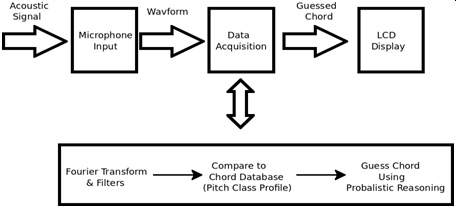
In the following sections I will discuss the final design and implementation that were used for my senior project. The following sub-sections will discuss the hardware implementation, the hardware integration, as well as the algorithm design and software. The figure below(Figure 3) shows the top- level schematic of the final implementation of the system
6.1 Hardware Implementation
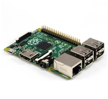
The first part of the hardware that had to be decided on was the component that would be performing the data acquisition as well as linking and integrating the other hardware components together. After considering various micro-controllers as well as an FPGA, it was decided that a Raspberry Pi Model B+ would be the most suitable choice for this project; the Raspberry Pi includes 4 USB ports, GPIO (General Purpose Input Output) pins, an Ethernet port, as well as the ability to have an underlying operating system on the device (which would make it easy to integrate devices, drivers, as well as program the device remotely). The following figure(Figure 4) shows a picture of the Raspberry Pi model that was purchased and used.
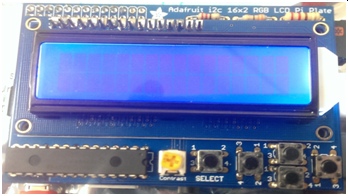
The second piece of hardware that had to be decided on was the component that would be responsible for displaying the output of the device. Since the output that needed to be displayed is simple and can be easily represented solely with ASCII characters, the need for an elaborate or large display was deemed unnecessary. The hardware that was decided on was a LCD 16×2 Character Display that included push buttons. The push buttons would prove to be very useful during the debugging process as well as for controlling the input to the device. Once the LCD display was purchased and arrived, it needed to be assembled and soldered together. Once this had been done, the display was abled to be attached to the Raspberry Pi by way of the GPIO pins. The following figure(Figure 5) shows a picture of the display that was used after being attached to the Raspberry Pi.
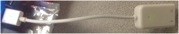
The final piece of hardware that was decided on was the the piece of hardware that would be responsible for handling the acoustic input to the device. The device had to be chosen in accordance with the design requirements for the input which included the input not needing to be amplified as well as not being of a symbolic data format such as MIDI. The first choice that was chosen was the Wolfson Audio Card which offers a high-quality audio input jack as well as a direct connection the Raspberry Pi. However, this was not able to be used because in the newer versions of the Raspberry Pi (like that was purchased and used) the 8-pin GPIO audio header has been removed so an alternative solution had to be sought out. After considering alternative ways to receive an auditory input to the Raspberry Pi and since the Raspberry Pi does not offer a line-input jack by itself, it was decided that a USB sound card would be used. A USB sound card would be accurate enough to receive non-amplified signal through a microphone for data acquisition and also be very easy to attach. The tricky part would then be working on integrating the USB sound card with the rest of the system, however since the Raspberry Pi has an underlying operating system running on it, this meant that this could be done through the operating system. The following figure(Figure 6) shows a picture of the USB sound card after being attatched to the Raspberry Pi, that was purchased and used for the project.
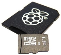
There were two other hardware components that were used for this device, however these components came as a result of selecting the rest of the hardware. The first component was a micro-SD card. The micro-SD car was used as memory for the Raspberry Pi which stored the operating system as well as all the other files and drivers on the Raspberry Pi. An 8gb micro-SD card was chosen and purchased which was considered to be enough memory for the project. The following figure(Figure 7) shows a picture of the micro-SD card that was purchased and used.
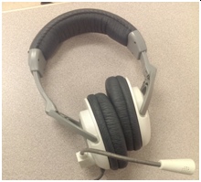
The final hardware component that was needed for this project was a microphone that would be plugged into the USB Sound card. Since one of the design requirements was portability, cost affordable, as well as being able to operate independently of user and location. For these reasons it was decided that instead of purchasing an expensive and bulky microphone that a simple headset microphone would be used instead. The following figure(Figure 8) shows a picture of the headset and microphone that was used for acquiring the auditory input to the USB sound card for the project.
The following section will discuss how these devices were integrated together using software along side the Raspberry Pi.
6.2 Hardware Integration
The first step that was needed to be done in order to integrate the hardware was deciding what operating system that the Raspberry Pi should run on. After considering various operating systems that have been made for the Raspberry Pi such as NOOBS and RISC OS, it was decided that Raspbian would be used. Raspbian is a debian based distribution of Linux made specifically to optimize the hardware of the Raspberry Pi; having a version of Linux installed as the operating system would greatly reduce the learning curve of learning a new operating system entirely as well as allow for drivers to be made more accessible (if a version of the driver already exists for a version of Linux).
Installing and setting up the Raspberry Pi with the Raspbian OS was a fairly simple task. First, the image file of the operating system had to be loaded on to the micro-SD card, which was done by using a program called “Pi-Baker” on another computer which contained a card reader. Once this had been done, the micro-SD card was inserted into the Raspberry Pi, an external screen was connected using an HDMI cord, and a keyboard and mouse were connected to the Raspberry Pi by way of the USB ports. Once the raspberry Pi was given power, a setup screen was displayed on the screen that was easily navigable by using the keyboard and mouse.
Once the operating system had been configured, the IP Address for the Raspberry Pi was found by using the ‘ifconfig' command in terminal which would allow the Raspberry Pi to be accessed remotely by the ‘ssh' command from a laptop. This was useful because it allowed for the project to be worked on without having a screen, mouse, or keyboard attached to the Raspberry Pi but it also meant that everything would be done from command line.
The next step that was done was integrating the display system with the Raspberry Pi. Once the LCD Display had been assembled and soldered it was connected by simply plugging the male ports of the display into the female GPIO ports on the Raspberry Pi. In order to get the display working with the Raspberry Pi in a python program ‘python-smbus' and ‘i2c-tools' must be installed using the
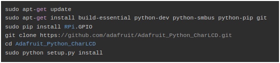
‘> sudo apt-get install' command in terminal. Once these dependencies have been installed, the i2cdetect program can be called by typing ‘> sudo i2cdetect -y 0' into terminal. This will detect the pins that are attached to the GPIO pins; if 0x20 appears in the window then the the LCD display is connected. Next, a few more dependencies must be installed in order to easily access the display. The following figure(Figure 9) shows a screen shot from the Adafruit website of the commands needed in order to install the LCD Display for use in python scripts.
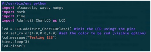
The Adafruit_Python_CharLCD library comes with example codes as to how to control the messages displayed on the LCD display as well as how to retrieve push button information, so from these examples a basic understanding of how the library works was easily deduced. The following
figure(Figure 10) shows python code that initializes and displays a simple message on the LCD display. The contrast of the LCD display was adjusted using a screwdriver to turn the yellow contrast dial until the message was completely visible.
The final step that needed to be done in order for all of the hardware to be integrated together was getting the USB Sound Card working with the Raspberry Pi and being able to control it from a python script. This was done by way of using the ALSA (Advanced Linux Sound Architecture) audio drivers. The first step was to make sure the drivers were installed by typing the following command into terminal: ‘> apt-get install libasound2 alsa-utils alsa-oss ‘. After the drivers have been installed, they must be tested to see if they are working properly which can be done by attaching a microphone to the input and headphones to the output of the USB Sound Card, making a short recording, and then playing it back to see if something was being properly recorded. This is done by using the following 2 commands:
“> arecord -f SIG_LE -r 16000 -D default > test_record.wav” “> aplay test_record.wav”
However, this did not initially work because the ALSA driver was prioritizing the on-board sound of the Raspberry Pi above the USB Sound Card. After trying to debug this problem using the ALSA mixer with the user interface, it was found that the problem needed to be fixed by editing a
driver file. By editing the file “/etc/modprobe.d/alsa-base.conf” and changing the line:
“options snd-usb-audio index = -2” to “options snd-usb-audio index = 0” the problem was fixed and after rebooting the system was tested using the commands listed above.
Once the ALSA drivers had been seen to be working, the python library for ALSA had to be installed which was done by using the terminal command: ‘> sudo apt-get install python-alsaaudio' The python module was tested by writing a short python script which made a recording. A simple python script incorporating the ALSA library can be seen in the following figure(Figure 11):