-Create a civilian's Tesla driving experience
Ⅰ.summary
By the end of 2019, the number of electric bicycles in China has reached 300 million, becoming an indispensable transport in the lives of the general public. However, the original dashboard is very simple, and the only information provided is electricity, speed and steering, which can no longer meet the requirements of people pursuing quality of life in the information explosion era.
In this paper, we develop a powerful display and control terminal for electric bicycles. The program uses STONE-STVC070WT HMI screen as the display control platform, and based on the C8051F340 chip developed a set of data acquisition, processing terminal, integrated a variety of sensor technology, to create not only can provide speed, power, steering information, and additional RTC clock, heading, environmental temperature, mileage data and other information, the user through the touch screen to complete the Driving mode and personalized lighting settings, and the ability to automatically turn on the lighting system and other functions.
Let your car has the same as the Tesla, full of technology display control terminal.
Ⅱ.The realization of the function
Let's show you our powerful feature list.
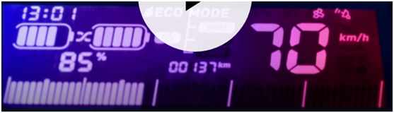
1. speed display function, display the vehicle speed from 0-100Km (basically will not be achieved), the display is familiar and like the car dashboard, and with numbers intuitive and simple.
2.Power display function, not simply mapping out inaccurate power information according to the battery voltage, but through the lithium battery discharge curve to calculate the real energy storage data, which is clearly shown to you through the battery icon and percentage data.
3.Turning information function, receives the user's steering control information, on the one hand, gives the steering tips on the display, on the other hand, drives the 5050 RGB light set, completes the personalized turn signal drive work.
4.RTC clock function, which provides accurate clock display function for your car, eliminating the trouble of looking at your cell phone or watch while riding your bike, and also provides the safety factor for your driving.
As a lady and program ape, you may have already got used to the city life, and gradually lost the sensitivity to the direction, the program in this article will provide you with real-time direction guide, refuse to find the embarrassment of the north.
6. Ambient temperature function, to provide you with 2 ℃ within the accuracy of the ambient temperature information, combined with the human body in the course of travel, timely addition of clothing.
7. A variety of mileage data functions, providing cumulative mileage, single driving mileage, battery remaining mileage data, you know your riding data like the back of your hand, but also to avoid getting yourself into the embarrassment of a dead trolley.
8. Driving mode settings, through the HMI touch screen, the user can set the cruise mode, sport mode, energy-saving mode, let you feel more than 300,000 B-class car mode experience.
9. personalized lighting settings, also via the HMI touchscreen, where you can select your preferred lighting and turn light modes.
Ⅲ.System principle and composition
The system mainly consists of two parts, the front-end display and control platform and the back-end data acquisition and processing platform, the specific realization principle is as follows.
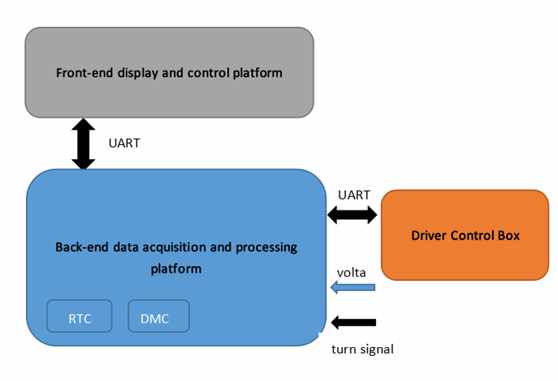
STONE HMI screen as a display control platform, receive various types of information sent from the back-end data acquisition and processing platform, and its display on the screen through a variety of controls, and at the same time on the user's touch operation feedback, give the corresponding instructions sent to the back-end data acquisition and processing platform.
The back-end data acquisition and processing platform communicates with the front-end platform and EV control box through the UART port of C8051F340 chip; uses the IIC interface and UART port to communicate with the on-board RTC clock module and DMC digital compass module to obtain the current time and heading information; reads the battery voltage through the ADC peripheral of the chip, calculates the electricity information through the discharge curve table, reads the battery voltage, and then reads the battery voltage through the DMC digital compass module. Analog voltage for speed, calculate the current speed and integrate the mileage data; the chip reads the steering key information; and through the chip's own temperature sensor, obtains the current chip temperature information. The photoresistor is collected and the lighting is automatically turned on according to the threshold value.
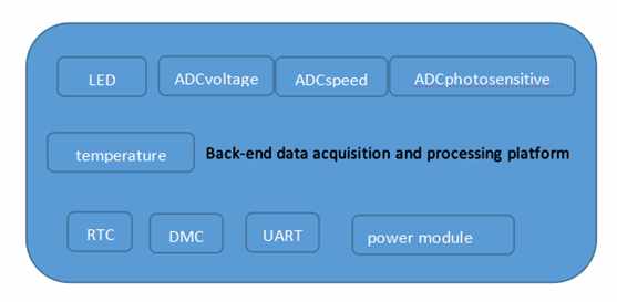
Back-end system components: MCU, photosensitive module, RTC module, DMC compass module, 5050RGB module, battery level and speed acquisition module, communication module.
IV. System hardware design
1. Front-end hardware design of graphics control
1.1 STONE HMI Module
This paper uses HMI screen from Beijing STONEn Technology Co. model STVC070WT-01, which integrates TFT display and touch controller. It includes processor, control program, drive, flash memory, RS232/RS485/TTL port, touch screen, power supply, etc., which is a powerful and easy-to-operate overall display system operating system that can be controlled by any microcontroller. The user interface is enriched with features such as text display, image display, curve display, and touch, video and audio playback. The built-in flash memory can store data, configuration files, images and so on.
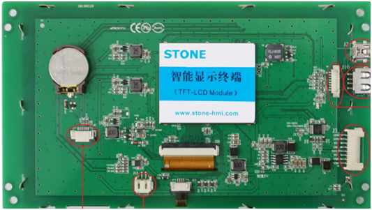
(1) STVC070WT-01 product features
-Controlled by any MCU.
-Display pictures/text/curves.
-65536 color TFT displays.
-With/without touch screen.
-RS232/RS485/TTL UART interface and USB port.
-Wide voltage range.
(2) Scope of application
Widely used in various industrial fields, medical and beauty equipment, construction machinery and vehicle equipment, electronic instruments, industrial control systems, power industry, civil electronic equipment, automation equipment, transportation.
1.2 Electrical connections.
(1) Power supply
The HMI screen is powered by a start-up current of 5V 600mA or more, which is generated in part by the Buck buck buck circuit of the back-end data acquisition and processing platform, as shown in the schematic diagram in the following section.
(2) Communications
The HMI display terminal uses UART port to communicate with the backend platform, because the model I use is STVC070WT-01, suffix-X1 (X=0 RS232, X=4 RS485, X=1 TTL), so it communicates with the TTL UART interface, the baud rate is set to 9600bps.
1.3 Development steps.
Using the STVC070WT's TFT-LCD module requires only four steps.
(1) Designed a nice set of “graphical user interfaces” using TOOL-2019 development software.
(2) Downloading the edited GUI to the TFT-LCD screen through the debugging tool.
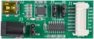
(3) Direct connection to the customer's MCU via RS232, RS485 or TTL levels.
(4) Write a simple program on the MCU side to let the MCU control the TFT-LCD module (hex code) by command and that's it.
2. Hardware design of the acquisition console
2.1 Hardware circuit diagram and its description
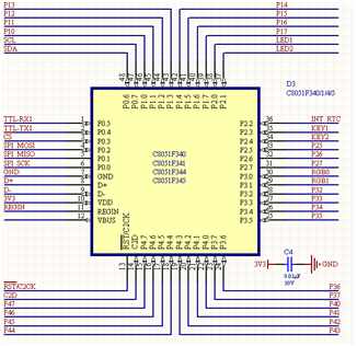
(1) The main control chip adopts C8051F340 to draw out the required IIC, UART, GPIO, etc. respectively.
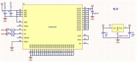
(2) The system power supply uses LTM8073 chip as the primary power supply to convert 48V to 5V output and LM1117-3.3V as the secondary power supply to convert 5V to 3.3V.
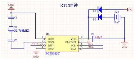
(3) RTC clock module, using PFC8563 clock chip, and with coin cell batteries as a backup power supply, to ensure that the system's real-time clock works properly for a long time.
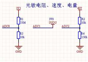
(4) photosensitive module, battery power module, speed acquisition module, photosensitive module adopts 5506 photosensitive resistor, the resistance is below 1k when sensitive to light, no light is above 1M; the speed of the electric car is 1-3V analog quantity can be directly collected; battery voltage is maintained between 42-48V, after 16 points of voltage control within 3V total microcontroller ADC collection.
(5) Connectors have C2 interfaces, key interfaces,
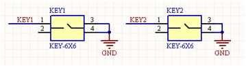
(6) Left and right steering button connections.
2.2 Main Control Chips
The C8051F340 is an 8051-compatible microcontroller core (up to 48 MIPS) with full-speed, non-intrusive in-system debug interface (on-chip), USB function controller, integrated transceiver and 1K FIFO RAM in a high-speed, pipelined architecture for mixed-signal system-on-a-chip microcontrollers from Silicon, with the following resources.
Power regulator.
A true 10-bit 200 ksps single-ended/differential ADC with analog multiplexer.
On-chip voltage references and temperature sensors.
On-chip voltage comparators (two).
Precisely calibrated 12MHz internal oscillator and 4x clock multiplier.
Up to 64 KB of on-chip FLASH memory.
Up to 4352 bytes of on-chip RAM (256+4KB).
Hardware-implemented SMBus/ I2C, enhanced UART (up to two) and enhanced SPI serial interfaces.
4 general purpose 16-bit timers.
Programmable counter/timer array (PCA) with 5 capture/comparison modules and watchdog timer functionality.
It fully meets the system resource requirements of 3-ADC, on-chip temperature sensor, hardware IIC and dual UART interface.
Ⅴ.System software design
1. Front-end software design for display and control.
(1) Development process
First, create the project and load the required images into the project, the format of the main images.
Second, create, using TOOL-2019 controls, dynamically associated relationships.
Third, software simulation, compilation and generation of executable files.
Fourth, connect the HMI screen to the PC via the debugging tool and download the executable file to the screen.
(2) How to create a dashboard.
(3) How communications are handled, to be clear, to give instructions.
2. Acquisition console software design.
(1) ADC programming.
void ADC_REF_TEMP_Set(bit temperature,bit biase,bit vref_out)
{
if(VREF_SOURCE_SET==VDD_VALUE_3D3V)
{
REF0CN = (0x08) | ((u8)temperature<<2)|((u8)biase<<1)|(vref_out);
}
else if(VREF_SOURCE_SET==VREF_VALUE_2D4V)
{
REF0CN = ((u8)temperature<<2)|((u8)biase<<1)|(vref_out);
}
}
u16 ADC_Measure(u8 input_p,u8 input_n,u8 times)
{
u16 temp;
u16 accumulation;
u8 i;
u8 killwhile;
AMX0P = input_p;
AMX0N = input_n;
ADC0CF = 0xF8;
ADC0CN = 0x80;
temp=0;
accumulation=0;
killwhile=255;
Delay_ms(300);
for(i=0;i<times;i++)
{
AD0INT=0;
AD0BUSY=1;
while(!AD0INT&&(killwhile)){killwhile–;}
AD0INT=0;
AD0BUSY=0;
temp=(ADC0H<<8)+ADC0L;
accumulation+=temp;
Delay_ms(1);
}
temp=accumulation/times;
return temp;
}
float ADC_Calc_Volate(u16 MeasureValue,float Volate_Scale)
{
float temp;
if(VREF_SOURCE_SET==VDD_VALUE_3D3V)
{
temp=((float)MeasureValue/1024)*3.3;
}
else if(VREF_SOURCE_SET==VREF_VALUE_2D4V)
{
temp=((float)MeasureValue/1024)*2.4;
}
temp=temp*Volate_Scale;
return temp;
}
float Temperature_measure(void)
{
float temp;
u8 killwhile;
u8 times;
AMX0P = TEMP;
AMX0N = GND;
ADC0CF = 0xF8;
ADC0CN = 0x80;
temp=0;
killwhile=255;
Delay_ms(900);
for(times=8,temp=0;times>0;times–)
{
AD0INT=0;
AD0BUSY=1;
while(!AD0INT&&(killwhile)){killwhile–;}
AD0INT=0;
AD0BUSY=0;
temp+=(ADC0H<<8)+ADC0L;
}
ADC_REF_TEMP_Set(0,0,0);
temp = temp/8;
temp = (temp/1024*VREF_SOURCE_SET-0.776)/0.00286;
return temp-Temperature_Offset;
}
void Single_Write_HMC5883(uchar Address,uchar Dat)
{
IIC_Start();
HMC5883_Send_Byte(SlaveAddress);
HMC5883_Send_Byte(Address);
HMC5883_Send_Byte(Dat);
IIC_Stop();
}
{
uchar Value;
IIC_Start();
HMC5883_Send_Byte(SlaveAddress);
HMC5883_Send_Byte(Addr);
IIC_Start();
HMC5883_Send_Byte(SlaveAddress+1);
Value=HMC5883_Rec_Byte();
IIC_SendAck(1);
IIC_Stop();
return Value;
}
void Multiple_Read_HMC5883(void)
{
uchar i; IIC_Start();
HMC5883_Send_Byte(SlaveAddress);
HMC5883_Send_Byte(0x03); IIC_Start();
HMC5883_Send_Byte(SlaveAddress+1);
for(i=0;i<6;i++) {
Rec_Data[i]=HMC5883_Rec_Byte();
if(i==5)
IIC_SendAck(1); else
IIC_SendAck(0); }
IIC_Stop();
Delay(100);
}
X=Rec_Data[0]<<8 | Rec_Data[1];//Combine MSB and LSB of X Data output register
Z=Rec_Data[2]<<8 | Rec_Data[3];//Combine MSB and LSB of Z Data output register
Y=Rec_Data[4]<<8 | Rec_Data[5];//Combine MSB and LSB of Y Data output register
Angle= atan2((double)Y,(double)X)*(180/3.14159265)+180;
Angle*=10;
Acr=(uint)Angle;
VI. System performance testing