
The intention of the article is to highlight opportunities presented by incorporating simple modern digital methods in the design of SPRAT-style radios – not to promote one particular design.
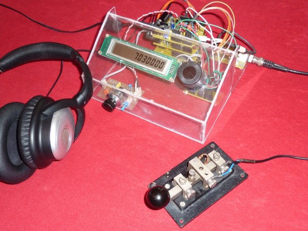
The ideas in the article have been demonstrated in the construction of a simple rig, a picture of which appears on the front cover of SPRAT 156 and is repeated here…
- it works (I've had lots of QSOs on 80, 40 and 30m with it)
- it embodies the “Occam's Microcontroller” ideas (and displays them through its transparent “enclosure”) and
- it provided me with hours of fun in pursuit of my “self-training in radio communications”
Further detailed descriptions of the important sub-systems within the rig appear below.
SOFTWARE
The arguments in the “Occam's Microcontroller” article are agnostic to the particular microcontroller being used. However, the article does describe the recent revolution in access to microcontroller technologies embodied in the “Arduino Electronics Prototyping Platform”. All the resources presented on this page (and used in the original rig) are expressed in the context of the Arduino.
Those with appropriate experience can use any number of alternative microcontrollers (such as PICs) or physical computing platforms (such as the Raspberry Pi) to good effect. But I recommend that beginners seeking to follow the “Occam's Microcontroller” ideas start with the Arduino.
You can learn about Arduino and download the Arduino software from here.
There are useful tips and tutorials, explaining how to get started here.
Don't be discouraged if you are new to digital systems – “The Arduino programming environment is easy-to-use for beginners, yet flexible enough for advanced users to take advantage of as well“.
Arduino programs are called “sketches”. There are many simple sketches for beginners on the Arduino website – but Radio Amateurs also should see my Iambic Keyer example, which will give opportunity to learn in a more relevant environment.
You can download the sketch which drives the original Occam's Microcontroller rig from here.
You can also find a sketch to run a quick test on the DDS module (setting it to 1 MHz output) here.
There's a new version of the Occam's Microcontroller rig, using a 16*4 alphanumeric display – description appears lower down this page.
There's an even newer, enhanced version of the rig, called “Occam's Dagger”, which is described here.
There is also a multi-mode beacon system, called (predictably enough) “Occam's Beacon”, which uses the physical resources already introduced to generate various beacon mode signals (QRSS and WSPR), as described here.
HARDWARE
The “Occam's Microcontroller” rig is built around a stack of four PCBs, as seen in the photo below. The bottom of the stack is an Arduino and the upper three boards are Arduino “Shields”…
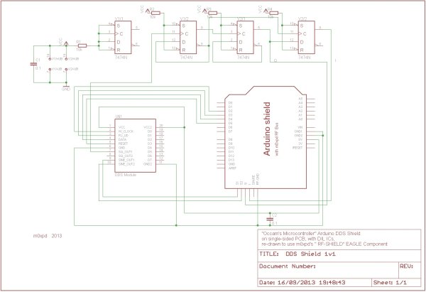
The DDS Shield
The Transmitter Shield
For more detail: The Occam's Microcontroller Rig