
I discovered the “Build A Simpsons TV” article in the Volume 79 issue of Make: magazine. The article is by Brandon Withrow and he did an excellent job documenting the build process in the article and on a dedicated web site: www.withrow.io/simpsons-tv-build-guide. As I embarked building my own Simpsons TV, I ran into issues being able to obtain the 2.8″ display specified in the build instructions as well as audio and OS issues. So, I thought I would take my learnings and present them here for others who might find them useful. In the end, I built my Simpsons TV using a 3.5″ display available on Amazon, fixed the audio issues, and enhanced the functionality of the project by adding play/pause, rewind, next video, change “channel”, exit python script, and safe power shutdown features.

Of particular note is the safe power shutdown feature. The Raspberry Pi OS features a journaling file system. This means that it can be writing to the SD card at any time. This can potentially be bad if you just remove power without executing a proper shutdown sequence. How bad can this be? Well, let's just say that I've completely ruined several SD cards on Raspberry Pis before I learned this lesson (they had to be thrown away – nonrecoverable). To address this, I created a simple circuit using an Atmega ATtiny microcontroller to monitor the power switch, send a signal to the Pi to shutdown, monitor the activity LED signal on the Pi, then safely remove power from the Pi once all activity has ceased. There are other options to address the safe power shutdown needed by the Pi without using a dedicated microcontroller, which I'll also cover in this Instructable.
This Instructable is rather long due to me including a lot of low-level details about all the steps required to build this project. My intent is to provide a fun learning experience on topics such as 3D printing, ATtiny microcontrollers, Raspberry Pi, Python, some Arduino, and soldering. I hope you enjoy!
Now, let's get started…
Supplies
Most of the supplies are the same as those called out on Brandon's website. I've copied them here for completeness with modifications based on my build.
3D Printed Parts (https://www.thingiverse.com/thing:5257326):
- TV Housing
- TV Front
- VCR
- Antennae Balls (2x)
- Power Switch Actuator
- Power Switch Base
- Volume Knob
- Volume Knob Base
- TV Foot (4x – Front Left, Front Right, Rear Left, Rear Right)
- Front Grille
Electronic Parts:
- AC to DC power adapter – 5VDC @3A with micro USB output connector
- Raspberry Pi Zero 2 W
- iUniker 3.5-inch Raspberry Pi Zero display, 480 x 320 resolution (Amazon)
- Adafruit mono 2.5W class D audio amplifier board (Amazon)
- 64GB Ultra Micro SDHC memory card (Amazon)
- ATtiny25 microcontroller (NOTE: ATtiny45 or ATtiny85 will work as well – they have the same pinout and functionality, just more memory – any variant will work, just get the DIP package version: Amazon)
- 8-pin IC DIP socket (Amazon)
- 1k Ohm potentiometer (I bought a kit of multiple values: Amazon)
- 6mm x 6mm x 6mm push micro momentary push button (2x – kit of switches: Amazon)
- 7mm x 7mm push-on/off push button (included in the kit of switches above)
- Micro USB to DIP adapter (Amazon)
- Gikfun 4 Ohm 40mm diameter 3W speaker (Amazon)
- IRF4905 P-FET power transistor or similar (Amazon)
- 40-pin, 2 x 20, extended pin socket header (Amazon)
- PC Board
- 100 Ohm, 1/4 W resistor (included in resistor assortment kit: Amazon or similar)
- 220 Ohm, 1/4 W resistor (included in resistor assortment kit)
- 330 Ohm, 1/4 W resistor (2x) (included in resistor assortment kit)
- 0.1uF 50V ceramic capacitor (2x) (Amazon)
- 1N4148 rectifier diode (2x) (Amazon)
- 1 pin header (snap off larger header – crimp sockets and header pin kit: Amazon or similar)
- 2 pin header, 0.1″ spacing (2x) (snap off larger header from header kit above)
- 1 pin DuPont socket with female crimp pin (3x) (included with crimp socket kit above)
- 2 pin DuPont socket with female crimp pins (4x) (included with crimp socket kit above)
- 3 pin DuPont socket with female crimp pins (included with crimp socket kit above)
- Signal Wire (included with crimp socket kit above – usually 28 AWG)
- 22 AWG Wire – about 2 feet (half red/half black or similar: Amazon)
- ~1″ / 25mm of 30AWG solid wire (Amazon).
Tools & Misc Supplies:
- Soldering Iron
- Solder (I prefer Kester 0.020″ diameter 24-7068 lead-free as 60/40 Sn/Pb lead-based solders are toxic).
- Hot Melt Glue Gun
- Hot Melt Glue
- Super Glue (cyanoacrylate)
- Crimpers (for socket crimps – included with the crimp sockets and header pin kit mentioned above)
- Wire cutters
- Wire strippers
- Mini file set (with round and flat files – used to clean up 3D printed parts)
- Rustoleum Universal Paint and Primer gloss black spray paint or whatever paint you want to use to paint the bezel.
- Painter's tape (for masking off the bezel area for painting)
- Cotton swabs
- Isopropyl alcohol
- Programmer for ATtiny (Arduino UNO or dedicated programmer such as AVRISP mkII or similar)
- 10uF capacitor (for Arduino UNO if it is used to program the ATtiny)
- USB keyboard (to set up Pi)
- USB micro to USB B converter (if needed to connect keyboard and USB thumb drive to Pi)
- HDMI mini to HDMI converter (if needed to connect HDMI monitor to Pi)
- Breadboard (used to aid in programming the ATtiny microcontroller)
- DuPont wires (used to connect programmer to ATtiny on breadboard for programming) (Amazon)
- 1/4″ diameter x 1/16″ thick (6mm x 1.5mm) neodymium magnets (4x) (Amazon). Other similar sizes can be used, but you may have to modify the TV housing and TV front 3D model files to fit.
- #6 x 3/8″ machine screws (2x)
Step 1: 3D Design
The 3D STL files Brandon provided were for a 2.8″ screen version. Unfortunately, STL files are not ideal for the significant modifications I needed to make to fit my 3.5″ screen version. So, I went searching on Thingiverse for possible alternates that would fit my 3.5″ screen. I did not find anything that fit it directly. However, I found the next best thing! On Thingiverse, I found that highping had remodeled the 3D design for Brandon's Simpsons TV from the ground up for a 4″ HDMI screen – and – he was kind enough to include the Fusion 360 source files for his design. Also, his design featured two buttons on the VCR box that sits on top of the TV, so I was able to make use of those to implement the play/pause, rewind, next video, change “channel”, and exit Python script features (more on these later).
For my project, I made the following modifications to the Fusion 360 files from highping:
- Changed the display bezel area to accommodate my 3.5″ display
- Added screw holes to the VCR box and TV case to make it easy to service the buttons in the VCR should the need arise. This allows you to mount the VCR using two #6 x 3/8″ screws to the TV instead of gluing it.
- Changed the volume knob, volume knob base, power switch actuator, and power switch base to be compatible with the volume knob and power switch from Brandon's original design.
- Extended the top front alignment edge to traverse the entire front – this acts as a light block to prevent the display's backlight from bleeding out around the top gap between the TV housing and the TV front.
- Resized the circular holes for the speaker and the four magnets to fit the parts I had on hand.
- Added “foot stop” feature at the four bottom corners of the housing to act as secure stops and glue points for the four feet.
I have posted STLs, Fusion360, Autodesk 123D Design, and STEP file variants on Thingiverse (https://www.thingiverse.com/thing:5257326) to make it easy for most anyone to modify for their purposes.
Step 2: 3D Printing
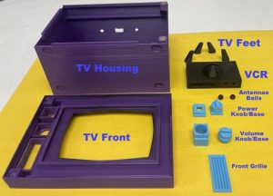
A total of (14) 3D printed parts are needed (reference 3D Printed Parts in the Supplies section). I printed everything using a 0.4mm nozzle, 0.2mm layer height, and 30% infill out of black, light blue, and purple PLA plastic (I used 3D Solutech plastic from Amazon – but most any PLA will do – use what works best for you and your 3D printer).
The picture shows the print orientation and color I used for each part. I didn't use any supports on the TV Housing, TV Feet, or Antennae Balls. I used minimal supports on everything else. I did not use any rafts, but printed multiple parts at the same time (or multiple copies) for smaller parts to allow some cooling time for each part in between printing layers – this helps improve print quality for the smaller parts (i.e. TV Feet, Knobs/Bases, Front Grille, and Antennae Balls).
After 3D printing, some light filing is usually needed around the base (where the part made contact with the 3D printer bed) or where support material meets a side edge of some of the parts (knobs/bases, front grille, VCR button holes, and antennae feet) in order for them to fit correctly with mating parts. I used a set of small files to do this. You can use a hot-air rework station after filing to remove the “whiting” effect of filing; Use minimal heat and quick passes of the hot air to prevent warping of the part. If you've never done this before, I suggest trying this on a piece of scrap 3D printed plastic to perfect your technique.
Step 3: Electronic Parts
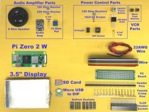
The picture above Provides a visual reference of all the electronic parts used in this build variant of The Simpsons TV.
Step 4: Raspberry Pi Zero 2 W Pinout & Resource Usage
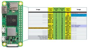
As you can see from the figure above, most of the Pi's GPIO pins are used by the LCD screen.
The usage entries with the shaded backgrounds indicate DuPont socket connectors used to connect power, audio, VCR buttons, and the safe shutdown signal (Pi pins 2, 4, 6, 10, 22, 23, 35, 37, and 39 are used) . Additionally, the Status LED signal will be used; but, it must be accessed via a test point on the back of the board.
Step 5: Wire Audio Amplifier Circuitry
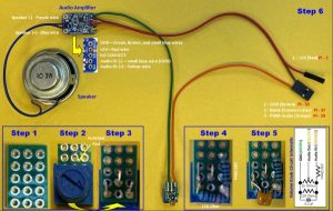
The audio output on the Raspberry Pi Zero 2 W is generally provided via PWM signals on GPIO18 and GPIO19. This project only uses one channel of audio, so it only uses GPIO19 and a mono audio amplifier. The original design uses this same approach, but I changed the audio circuit to:
- Reposition the 1k Ohm volume potentiometer from the output side of the audio amplifier to the input side. This is because these small potentiometers can be damaged by the larger current that they can be exposed to on the audio output side (at high volume / low resistance). Moving the volume potentiometer to the input side of the amplifier greatly reduces the current to which the volume potentiometer may be exposed.
- Added a Volume Knob circuit to address the “tinny” and scratchy audio issue. This circuit is comprised of a 100 Ohm resistor, 220 Ohm resistor, and 0.1uF capacitor (Note: The 1k Ohm volume potentiometer was added to the output of this circuit to provide the volume control on the input side of the audio amplifier). These components create a filter for the harsh PWM audio signal to smooth it out before feeding it into the audio amplifier. This greatly improves the audio quality.
The picture above shows the six steps to build the audio circuit. Steps one through five show the construction of the volume knob circuit while step 6 shows how to wire the complete audio circuit (volume control knob circuit, audio amplifier, speaker, and Raspberry Pi connectors). Details for each step are as follows:
- Step 1 – Cut a piece of the PC Board so that it is 3 holes wide by 5 holes high as shown in Step 1. This PC Board will be used to build the volume knob circuit.
- Step 2 – Position the 1k Ohm potentiometer on the 3 x 5 piece of PC Board. The orientation of the potentiometer matters as the knob is NOT centered top-to-bottom (but it IS centered side-to-side); note the position of the notched end of the potentiometer shown in Step 2.
- Step 3 – Flip the PC Board over, make sure the pins of the potentiometer are positioned as shown in the Step 3 picture, then solder the three pins.
- Step 4 – Solder the 220 Ohm resistor across the two outermost pins of the potentiometer on the bottom side of the PC Board. Then, solder one end of the 100 Ohm resistor to the right pin of the potentiometer/220 Ohm resistor junction. Insert the other end of the 100 Ohm resistor in the 4th hole as shown in the Step 4 picture – solder in place. Trim all component leads using flush-cut wire cutters.
- Step 5 – Solder the 0.1uF capacitor across the 220 Ohm resistor leads as shown in the Step 5 picture. Trim the capacitor leads.
- Step 6 – Use 28 AWG signal wire to wire the speaker, audio amplifier board, volume knob circuit and Raspberry Pi connectors as shown in the Step 6 picture:
- Wire the speaker to the amplifier with two signal wires about 4″ long (Purple and Blue). Solder all ends.
- Solder one end of a ~1/2″ piece of 30AWG solid wire (small blue wire) to the audio amplifier's Audio IN(-) connection. Place the other end in of the 30AWG wire into the GND hole on the audio amplifier (BUT DO NOT SOLDER YET! – two more wires will need to be inserted into this hole before soldering).
- Solder three signal wires (Green, Yellow, and Orange) about 6″ long to the volume knob circuit board; one wire to the GND connection (Green), one wire to the Audio OUT connection (Yellow), and one wire to the Audio IN(+) connection (Orange). Crimp a female crimp pin on the other end of the Audio IN(+) wire (Orange) and then insert it into position 3 of a 3-position socket connector as shown in the picture.
- Solder the other end of the Audio OUT wire (Yellow) from the volume knob circuit to the Audio IN(+) connection on the amplifier board.
- Cut two more signal wires (Red and Brown) about 6″ long and solder one (Red) into the +5V power connection on the audio amplifier board. Crimp a female crimp pin on other other end of this wire and insert the female crimp pin into a 1-position socket connector. Insert the other wire (Brown) into the audio amplifier board's GND connection hole along with the existing 30AWG solid wire (small blue wire) previously inserted there and the GND wire from the volume knob circuit (Green) – solder all three wires in this hole. On the other end of the audio amplifier GND wire (Brown), crimp a female crimp pin and insert it into position 1 of the 3-position socket as shown in the picture above.
NOTE: Of course, you can use whatever colors you like for the wiring scheme. The colors are mentioned here to match the pictures so that it's easier to keep track of what wire goes where.
Step 6: Getting Ready to Program the ATtiny for Safe Shutdown Circuit
The ATmega ATtiny microcontroller can be programmed using the Arduino IDE. But, The Arduino IDE does not have this capability natively. So, this must be set up first. If you don't have the Arduino IDE, install it by going to Arduin.CC.
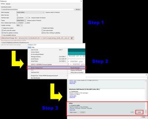
- Step 1 – Open the Arduino IDE and select File -> Preferences. In the “Additional Manager URLs:” field, copy/paste the following URL: https://raw.githubusercontent.com/damellis/attiny/ide-1.6.x-boards-manager/package_damellis_attiny_index.json as shown in the first picture above.
- Step 2 – Click “OK“. Next, click on Tools -> Board -> Board Manager as shown in the picture above.
- Step 3 – In the Board Manager, scroll down the list to where it says “attiny by Davis A. Mellis“. Click on that and then click “INSTALL“.
This should add new entries in the Tools -> Board menu. However, there is additional functionality needed that is not installed by the attiny package.
Step 7: Adding Programming Brownout Protection Capability to the Arduino IDE
Even though the attiny package provides the ability to program the ATtiny microcontroller, it's abilities to program configuration options are limited to just selecting the system operating frequency of the microcontroller; it does not provide a way to set brownout protection options. If brownout protection is not enabled, it might be possible to corrupt the microcontroller's memory if voltage powering it falls below required operating levels. An external voltage monitor could serve this function as well, but why add the cost when the functionality is provided within the ATtiny itself? Luckily, adding the required functionality to the attiny package is easily accomplished.
There are three Fuse Bytes within the ATtiny that configure different options such as system clock source, brownout detection enable/disable and level, watchdog timer enable/disable, external reset enable/disable, and self-programming enable/disable to name a few. To enable brownout protection, the proper value must be programmed into the Fuse High Byte of the ATtiny microcontroller. If you want, you can read more on the ATtiny system architecture by reading the datasheet.
The attiny package provides the ability to program these three Fuse Bytes using the “Burn Bootloader” command in the “Tools” menu. But, the options are limited to just specifying the system clock source. Fortunately, it is simple to add the ability to program brownout detection and its level by making a simple modification to the “boards.txt” file installed by the attiny package. To do this, navigate to the “boards.txt” file in the “…/Arduino15/pacakages/attiny/hardware/avr/1.0.2/” directory on your computer. On a windows PC, this is usually located at the following location:
“C:\Users\<user>\AppData\Local]Arduino15\packages\attiny\hardware\avr\1.0.2\”
where “<user>” is the user profile logged into the computer and “1.0.2” is the version of the attiny package installed.
Once you have located the “boards.txt” file, open it in a text editor such as Notepad, Wordpad, Notepad++ or other. Locate and replace the following text:
ATtinyX5.menu.clock.internal8=Internal 8 MHz
ATtinyX5.menu.clock.internal8.bootloader.low_fuses=0xe2
ATtinyX5.menu.clock.internal8.bootloader.high_fuses=0xdf
ATtinyX5.menu.clock.internal8.bootloader.extended_fuses=0xff
ATtinyX5.menu.clock.internal8.build.f_cpu=8000000L
with the following text:
ATtinyX5.menu.clock.internal8a=Internal 8 MHz, No BOD
ATtinyX5.menu.clock.internal8a.bootloader.low_fuses=0xe2
ATtinyX5.menu.clock.internal8a.bootloader.high_fuses=0xdf
ATtinyX5.menu.clock.internal8a.bootloader.extended_fuses=0xff
ATtinyX5.menu.clock.internal8a.build.f_cpu=8000000L

ATtinyX5.menu.clock.internal8b=Internal 8 MHz, BOD = 1.8V
ATtinyX5.menu.clock.internal8b.bootloader.low_fuses=0xe2
ATtinyX5.menu.clock.internal8b.bootloader.high_fuses=0xde
ATtinyX5.menu.clock.internal8b.bootloader.extended_fuses=0xff
ATtinyX5.menu.clock.internal8b.build.f_cpu=8000000L

ATtinyX5.menu.clock.internal8c=Internal 8 MHz, BOD = 2.7V
ATtinyX5.menu.clock.internal8c.bootloader.low_fuses=0xe2
ATtinyX5.menu.clock.internal8c.bootloader.high_fuses=0xdd
ATtinyX5.menu.clock.internal8c.bootloader.extended_fuses=0xff
ATtinyX5.menu.clock.internal8c.build.f_cpu=8000000L

ATtinyX5.menu.clock.internal8d=Internal 8 MHz, BOD = 4.3V
ATtinyX5.menu.clock.internal8d.bootloader.low_fuses=0xe2
ATtinyX5.menu.clock.internal8d.bootloader.high_fuses=0xdc
ATtinyX5.menu.clock.internal8d.bootloader.extended_fuses=0xff
ATtinyX5.menu.clock.internal8d.build.f_cpu=8000000L
Save the file and exit. If you notice, only the high_fuses value is changed in each of the four code groups added above (the low_fuses and extended_fuses values are all the same). These four groups of code replace the one “Internal 8 MHz” clock selection option in the menu tree with four new menu options as follows:
- Internal 8 MHz, No BOD – This is the same as the original “Internal 8 MHz” option
- Internal 8 MHz, BOD = 1.8V – This option selects the Internal 8 MHz option AND enables 1.8V Brownout detection
- Internal 8 MHz, BOD = 2.7V – This option selects the Internal 8 MHz option AND enables 2.7V Brownout detection
- Internal 8 MHz, BOD = 4.3V – This option selects the Internal 8 MHz option AND enables 4.3V Brownout detection
That's it – we're all done with this step. Moving on…
Step 8: Program the Arduino UNO As an In-system-programmer
There are multiple ways of programming the ATtiny microcontroller. Probably the least expensive and most accessible way is to use the Arduino IDE with an Arduino UNO as an In-System-Programmer (ISP). So, that is the approach I'm going to take in this instructable.
The first step is to set up an Arduino UNO as an ISP. To do this:
- Connect an Arduino UNO to your computer
- Open the Arduino IDE
- In the Arduino IDE, select File -> Examples -> ArduinoISP
- Upload to the Arduino using the “Upload” button on the menu bar or by selecting Sketch -> Upload in the Arduino IDE
At this point, the Arduino UNO is an ISP. Remove power (USB cable) from the Arduino UNO so that you can wire it up to the ATtiny microcontroller on a breadboard as detailed in the next step.
Step 9: Wire the Arduino UNO ISP to the ATtiny for Programming
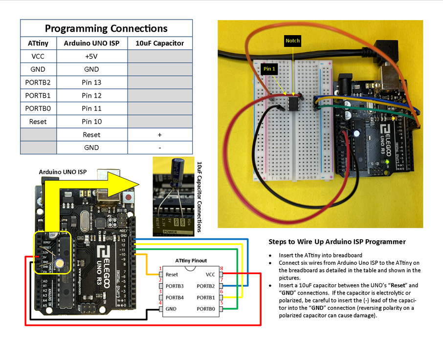
Following the picture above, perform the following steps to wire up the Arduino UNO ISP to the ATtiny microcontroller to prepare for programming:
- Insert the ATtiny microcontroller into a breadboard. Note the end of the ATtiny with the notch or the dot – the pin to the left of the notch or dot is pin 1. The pin numbers are in sequence and go in a circle counterclockwise to pin 1 (reference the ATtiny pinout shown in the bottom of the picture).
- Connect six DuPont style (or appropriately sized solid) wires from the Arduino UNO ISP to the ATtiny on the breadboard as shown in the picture and detailed in the “Programming Connections” table.
- Insert a 10uF capacitor between the Arduino ISP's “Reset” and “GND” connections as shown in the picture. If the capacitor is electrolytic or polarized, be careful to insert the (-) lead of the capacitor into the “GND” connection of the UNO (reversing polarity on a polarized capacitor can cause damage!). This capacitor is used to prevent the UNO from auto-resetting during programming operations of the ATtiny.
That's it – pretty simple. Now on to programming the ATtiny…
Step 10: Program the ATtiny Microcontroller
Finally, it's time to program the ATtiny25, 45, or 85 microcontroller. This occurs in two sequences; one to program the configuration fuses (this has to occur first as it erases the program area of the microcontroller) and the second is to program the actual program. So, let's get started.
First, we program the configuration fuses:
- Connect the Arduino UNO ISP to the USB port of your computer.
- Open the Arduino IDE and select Tools -> Board -> ATtiny Microcontrollers -> ATtiny25/45/85
- In the Arduino IDE, select Tools -> Processor -> ATtiny25 (or ATtiny45 or ATtiny85)
- In the Arduino IDE, select Tools -> Clock -> Internal 8 MHz, BOD = 2.7V
- Select COM port of the Arduino UNO ISP by selecting Tools -> Port -> <COM PORT of UNO>
- In the Arduino IDE, select Tools -> Burn Bootloader
- Once complete, you should get a message in the Arduino IDE message window stating, “avrdude done. Thank you.“. If you get errors, check your connections and try again.
- If you get nothing in the Arduino IDE message window, click on File -> Preferences and make sure the “upload” checkbox is checked for the “Show verbose output during:” parameter
Once you get the ATtiny configuration fuses successfully programmed, you will need to open up the Pi_Power Arduino sketch and upload it to the ATtiny. This is accomplished by the following actions:
- In the Arduino IDE, select File -> New. Select all (Ctrl-a) and hit the Delete key. Or, download the Pi_power.ino file attached to this step and save it in a directory named “Pi_power” (must match the same name as the “Pi_power.ino” file) and open this file in the Arduino IDE – if you do this, you can skip the next bullet.
- Copy the Pi_power C code provided below into the blank sketch in the Ardunio IDE. Save this file as “Pi_power.ino” on your computer.
- Upload the “Pi_power.ino” file to the ATtiny using the “Upload” button on the menu bar or by selecting Sketch -> Upload in the Arduino IDE
- Once complete, you should get a message in the Arduino IDE message window stating, “avr =dude done. Thank you.“. If you get errors, check your connections and try again.
- If you get nothing in the Arduino IDE message window, click on File -> Preferences and make sure the “upload” checkbox is checked for the “Show verbose output during:” parameter
That's it! – you're all done programming the AT =tiny microcontroller. Power down the Ar =dunio UNO ISP now by unplugging the USB cable from it. Carefully remove the A =Ttiny from the breadboard and put it someplace safe while you solder up the power control board in the next step. You can put away the Arduino UNO and breadboard now – you won't be needing them anymore for this project.
Feel free to peruse the Pi_power.ino file in the Arduino IDE editor. The code is not too long and should be easy to understand as it is chock full of comments. Well, enough dabbling – on to building the power control circuit…
Pi_power.ino C code:
/*
//////////////////////////////////////////////////////////////////////
 Pi_power.ino
 Version: 1.0
 Author:  D.J. Hatfield
 Date:    2/6/2022
 Devices: ATtiny25, ATtiny45, ATtiny85
 Purpose: Controls power up and shutdown/power off sequences for a
          Raspberry Pi.  It monitors the Power_IN pin to determine when
          to power up the Raspberry Pi and issue a shutdown sequence on
          the Pi via the Pi_Shutdown pin.  Once a Shutdown has been
          initiated, the Pi_Status pin is monitored to verify when the
          Pi has completed its shutdown sequence and no more disk
          activity is occurring on the Pi's SD card.  Once no activity
          is detected for 1 Second, power is removed from the system.
          Power is restored once the Power up signal is observed on the
          Power_IN pin. Power is controlled via the Power_OUT pin.
////////////////////////////////////////////////////////////////////////
*/
//Define physical inputs and outputs
//Power_IN - connect to push ON/OFF power button switching GND
//Power_OUT - connect to Power P-FET through 330 Ohm resistor
//Pi_Status - connect to LED activity signal from Pi (soldered to test pad on Pi)
//Pi_Shutdown - connect to input-with-pullup pin on Pi to initiate Shutdown
//              requires Python script to be running on Pi to monitor this signal
//              and initiate a shutdown.
#define Power_IN  B00010000   //PORTB4 pin INPUT - Active LOW indicates to power ON
#define Power_OUT  B00001000  //PORTB3 pin OUTPUT - Active LOW turns power ON
#define Pi_Status  B00000100  //PORTB2 pin INPUT - Active LOW indicates Pi activity
#define Pi_Shutdown B00000010 //PORTB1 pin OUTPUT - Active HIGH initiates Pi shutdown


//Define named states for the overall control state machine.  State machine sequence
//is 0-1-2-3-4-0...
#define Power_OFF 0     //Power is OFF state
#define Power_ON 1      //Power is ON state
#define Power_Delay 2   //Power Delay state - used to wait several mS after initiating
                        //a shutdown command before starting to check the Pi_Status
                        //signal
#define Powering_Down 3 //Powering Down state monitors Pi_Status for no activity for 1S
#define Power_Delay2 4  //Another power delay state used to allow pi to complete power
                        //down before allowing possibility of powering back up


//define variables used in this program
int State;            //Integer - keeps track of the controller's state machine
byte DebounceTimer;   //Byte - tracks number of milliseconds for input debouncing
int PiActivityTimer;  //Integer - tracks number of milliseconds for monitoring Pi_Status
//----------------------------------------------------------------------------------------
//setup:  Used to initialize processor - only executed once at startup or controller reset
//----------------------------------------------------------------------------------------
void setup()
{

   PORTB = B00010100;    //Enable resistive Pullup on inputs PORTB2 & PORTB4
   SetOutput(Power_OUT); //Insure power does not glitch ON during boot of controller
   DDRB  = B00001010;    //Set PORTB1 and PORTB3 as outputs


   //Configure Timer/Counter1 Control Register 1 (TCCR1)
   //CTC1 = 1   Clear Timer/Counter on Compare Match
   //PWM1A = 0  Disable PWM A
   //COM1A1:0 = 00 disconnect from output pin OC1A
   //CS13:0 = 0111 prescale select CK/64 (8MHz / 64) >> count every 8uS
   TCCR1 = B10000111;
   //setup OCR1C compare register to cause ISR to occur once every 1mS
   OCR1C = 125;         //125 * 8 uS = 1 mS
   TIMSK = B01000000;   //Enable Timer/Counter 1 Compare matchA interrupt
   DebounceTimer = 0;   //Initialize DebounceTimer to 0mS
   PiActivityTimer = 0; //Initialize PiActivityTimer to 0mS
   State = Power_OFF;   //Initialize state machine to Power_OFF state (state 0)
   SetOutput(Pi_Shutdown); //Initialize Pi_Shutdown signal pin to inactive state
   interrupts();        //Enable interrupts (start 1mS timer interrupts)
}
//----------------------------------------------------------------------------------------
//loop:  Loops continuously.  This is the main program - implements the controller's
//       state machine.
//----------------------------------------------------------------------------------------
void loop()
{
  //Powered OFF State - just wait for Power ON switch
  if(State == Power_OFF){
    if(CheckInput(Power_IN) == false){  //If Power_IN signal is active->debounce
      if(DebounceTimer >= 50){   //Debounce power ON command for 50mS
        ClearOutput(Power_OUT);  //Power is turned ON by clearing the output
        State = Power_ON;        //Go to Power_ON state
        DebounceTimer = 0;       //Clear the Debounce Timer
      }
    }
    else{
      DebounceTimer = 0;         //Keep clearing Debounce Timer if Power_IN indicates
    }                            // Power_OFF (i.e. stay in the Power_OFF state)
  }
  //Powered ON State - just wait for Power OFF switch
  if(State == Power_ON){
    if(CheckInput(Power_IN) == true){  //If Power_IN signal is inactive->debounce
      if(DebounceTimer >= 50){  //Debounce power OFF command for 50mS
        State = Power_Delay;    //Go to Power_Delay state
        ClearOutput(Pi_Shutdown); //Initiate Shutdown of Pi
        DebounceTimer = 0;      //Clear the Debounce Timer
      }
    }
    else{
      DebounceTimer = 0;        //Keep clearing Debounce Timer if Power_IN indicates
    }                           // Power_ON (i.e. stay in the Power_ON state)
  }


  //Power_Delay State - Waits 100 milliseconds for Raspberry pi to start shutdown process
  //                    before starting to monitor Pi_Status.  This gives the Pi time to
  //                    get started with the shutdownprocess.
  if(State == Power_Delay){
    if(DebounceTimer >= 100){  //Use Debounce timer to simply wait for 100mS
      State = Powering_Down;   //Once 100mS timer times out, go to Powering_Down state
      PiActivityTimer = 0;     //Clear PiActivityTimer
    }
  }


 //Powering_Down State - Waits for Pi Activity to stop for >1S before shutting power OFF
 //                      to Raspberry Pi
  if(State == Powering_Down){
    if(CheckInput(Pi_Status) == true){  //If Pi_Status is inactive (i.e. HIGH), delay for
      if(PiActivityTimer >= 1000){      //  1S to insure all Pi activity is done
        State = Power_Delay2;           //Once 1S of no activity, go to Power_Delay2 state
        DebounceTimer = 0;              //Clear the Debounce timer
        SetOutput(Power_OUT);           //Power is turned OFF by setting the output
      }
    }
    else{
      PiActivityTimer = 0;              //Keep clearing PiActivity Timer as long as
    }                                   // activity is detected from the Pi
  }


  //Power_Delay2 State - Waits several milliseconds for Raspberry pi to complete power down before allowing possibility of powering back up
  if(State == Power_Delay2){
    if(DebounceTimer >= 100){     //Use Debounce timer to simply wait for 100mS
      State = Power_OFF;          //Once 100mS timer times out, go to Power_OFF state
      DebounceTimer = 0;          //Clear the Debounce timer
      SetOutput(Pi_Shutdown);     //Turn off the Pi_Shutdown signal now that Pi is OFF
    }
  }
}
//----------------------------------------------------------------------------------------
//CheckInput:  Reads PORTB input pin specified by byte "value" passed to it.  Returns TRUE
//             if the input is HIGH or FALSE if the input is LOW.
//----------------------------------------------------------------------------------------
bool CheckInput(byte value){
  if((PINB & value) == value){
    return true;
  }
  return false;
}
//----------------------------------------------------------------------------------------
//SetOutput:  Sets PORTB output pin specified by byte "value" passed to it.
//----------------------------------------------------------------------------------------
void SetOutput(byte value){
  PORTB = PORTB | value;
}
//----------------------------------------------------------------------------------------
//ClearOutput:  Clears PORTB output pin specified by byte "value" passed to it.
//----------------------------------------------------------------------------------------
void ClearOutput(byte value){
  PORTB = PORTB &~value;
}
//----------------------------------------------------------------------------------------
//Interrupt Service Routine:  Fires every 1mS.  Increments the DebounceTimer and
//                            PiActivityTimer variables once every 1mS.
//----------------------------------------------------------------------------------------
ISR (TIMER1_COMPA_vect)      //Interrupt vector for Timer1 - should fire every 1mS
{
  ++DebounceTimer;
  ++PiActivityTimer;
}
Attachments

Step 11: Build the Safe Shutdown Circuit
The Safe Shutdown Circuit utilizes the Atmega ATtiny25, 45, or 85 microcontroller to coordinate an ordered shutdown of the Raspberry Pi before removing power. You can use any one of these three microcontrollers to implement this circuit. They all have the same pinout and features. The only difference amongst them is the amount of RAM, Program Flash, and EEPROM memory they have. The ATtiny25 has the least and the ATtiny85 has the most. The program written for this project will easily fit in the smallest one.
It works by monitoring a signal from the power button that tells the microcontroller when to power the system up and when to power it down. When the power button indicates to power down, the ATtiny sends a signal to Raspberry Pi's GPIO11, which signals the player.py python script to execute a system shutdown command. After the ATtiny sends the shutdown signal, it monitors the status LED signal from the Pi to determine when the shutdown has completed. The ATtiny will turn power OFF to the system once the LED signal is inactive for > 1 second. The ATtiny will then monitor for a power up signal from the power button. Once it gets the power up signal, it applies power to the system. This safe shutdown circuit allows the Simpsons TV to independently control complete power ON/OFF functions of the system safely while still allowing the Pi to utilize a writable file system, which allows you to add/delete content from the Pi at any time without messing with any configuration options.
For most, this will be the most challenging part of this project due to the amount of soldering. Try to have patience as you work through it – the circuit is not that complex and parts are fairly minimal.
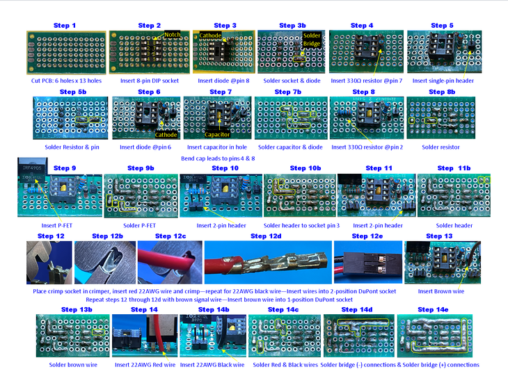
- Step 1: Cut a blank piece of PC Board 6 holes tall x 13 holes wide. You may want to leave extra on the ends to allow for easy mounting in the case with hot-melt glue.
- Step 2: Insert the 8-pin DIP socket as shown in the picture, leaving four holes to the left and five holes to the right. Note the notch in the DIP socket – It should be positioned toward the top. This notch indicates that pin 1 is to the immediate left. Pin numbering goes counter-clockwise as shown.
- Step 3: Insert one of the 1N4148 diodes as shown in the picture. The cathode end (the end with the black band) should go into the hole to the immediate right of pin 8 of the DIP socket. The other end should go in the hole above the cathode end. The purpose of this diode is to provide reverse polarity protection and, in conjunction with the 0.1uF capacitor, provide a filter to prevent the brownout detection from resetting the ATtiny when it applies power to the Pi, screen, and audio amplifier – the current surge at power-up can cause the 5V power rail to dip momentarily.
- Step 3b: On the back of the PC Board, solder all eight pins of the DIP socket and the two pins of the diode (clip the diode leads after soldering). Use additional solder to make a solder bridge between the diode’s cathode pin and pin 8 of the DIP socket. A lower soldering iron temperature (~550F / 288C for lead-free solder) and/or short applied heat time will help make the solder bridge easier to form.
- Step 4: Insert one of the 330 Ohm resistors as shown in the picture. One end should be in the hole to the immediate right of pin 7 of the DIP socket. The other end should be placed into the hole to the immediate right of the first pin of the resistor.
- Step 5: Insert a single-pin header to the immediate right of the 330 Ohm resistor as shown in the picture. This header pin will connect to the Status LED signal from the Pi.
- Step 5b: On the back of the PC Board, solder both pins of the 330 Ohm resistor and the one pin of the single-pin header (clip the resistor leads after soldering). Use additional solder to make a solder bridge between Pin 7 of the DIP socket and the closest pin of the 330 Ohm resistor. Create another solder bridge between the other pin of the 330 Ohm resistor and the single-pin header.
- Step 6: Insert the other 1N4148 diode as shown in the picture. The cathode end (the end with the black band) should be inserted into the hole to the immediate right of pin 6. The other end should be inserted into the hole to the immediate right of the first pin of the diode. This diode protects the Pi’s 3.3V “Shutdown” signal pin from the 5V signal level of the ATtiny. The Pi implements a pull-up to 3.3V for this signal and the ATtiny drives it to GND to indicate a command to shutdown.
- Step 7: Referencing the picture, insert the 0.1uF capacitor’s leads into the holes to the right of pins 2 and 3 of the DIP socket – the body of the cap will go into the hole located in the center of the DIP socket. Bend the leads of the capacitor so that one goes to pin 4 of the DIP socket and the other goes to pin 8 of the DIP socket.
- Step 7b: On the back of the PC Board, solder the pins of the 1N4148 diode and the 0.1uF capacitor (clip the diode’s leads after soldering – DO NOT clip the capacitor leads just yet). Use additional solder to make a solder bridge between the diode’s cathode pin and Pin 6 of the DIP socket. Solder one of the capacitor’s leads to pin 4 of the DIP socket and the other capacitor lead to pin 8 of the DIP socket as shown in the picture (clip the excess leads of the capacitor after soldering).
- Step 8: Referencing the picture, insert one lead of the other 330 Ohm resistor into the hole to the immediate left of pin 2 of the DIP socket. Insert the resistor’s other lead into the hole 3-positions to the left of the first lead. This resistor helps slow the turn-ON speed of the P-FET, which helps to minimize the current surge when turning on power to the Pi, Screen, and audio amplifier and it protects the ATtiny pin in case of a short circuit with the P-FET circuits. .
- Step 8b: On the back of the PC Board, solder the pins of the 330 Ohm resistor (clip the resistor’s leads after soldering. Use additional solder to make a solder bridge between pin 2 of the DIP socket and the resistor pin closest to it as shown in the picture.
- Step 9: Referencing the picture, insert the IRF4905 P-FET, side with part markings as shown, into three holes, skipping one hole to the immediate left of pin 1 of the DIP socket (the left-most pin of the P-FET should be in the same hole column as the end of the 330 Ohm resistor). The P-FET is used as a switch to turn ON/OFF power to the Pi, screen, and audio amplifier.
- Step 9b: On the back of the PC Board, solder the three pins of the P-FET (clip the two left-most leads of the P-FET [the GATE and DRAIN pins] – bend the third pin of the P-FET down and over as shown in the picture). Use additional solder to make a solder bridge between the left-most pin of the PFET (GATE pin) and the adjacent pin of the 330 Ohm resistor as shown in the picture.
- Step 10: Referencing the picture, insert a two-position header down one hole and to the left one hole from the immediate left of pin 4 of the DIP socket. This header will connect to the power switch.
- Step 10b: On the back of the PC Board, solder the two pins of the two-position header. Use additional solder to make a solder bridge trace between the left-most pin of the two-position header and pin 3 of the DIP socket as shown in the picture.
- Step 11: Referencing the picture, insert the other two-position header down one hole and to the right two holes from the immediate right of pin 5 of the DIP socket. This header will connect to incoming 5VDC power.
- Step 11b: On the back of the PC Board, solder the two pins of the two-position header.
- Step 12: Insert a DuPont female crimp socket into a crimping tool as shown in the picture. Gently close the crimp tool jaws to captivate the crimp socket.
- Step 12b: Slide the crimp socket as needed to make sure the back of the crimp socket is flush with the crimping die jaws.
- Step 12c: Strip about 0.1″ (2mm) from the end of a RED 22AWG wire (about 6″ / 15mm long) and insert that end into the crimp socket as shown in the picture. Be sure not to insert the wire too far; the insulation should only go far enough to be crimped by the insulation crimp (reference picture of Step 12d).
- Step 12d: Squeeze the crimp handles to crimp the female socket onto the wire. Open the crimper jaws after crimping and remove the female crimp socket form the jaws. Inspect to verify that the wire crimp portion of the female crimp socket is crimped around the bare wire and the insulation portion of the female crimp socket is crimped around the insulation of the wire as shown in Step 12d of the picture.
- Step 12e: Repeat steps 12 through 12d with a BLACK 22AWG wire (about 6″ / 15mm long). Insert the female crimp socket ends of the RED and BLACK wires into a 2-position DuPont socket as shown in Step 12e of the picture. Repeat steps 12 through 12d with a BROWN signal wire (about 6″ / 15mm long). Insert the female crimp socket end of the BROWN wire into a 1-position DuPont socket.
- Step 13: Strip about 1/8″ / 3mm from the other end of the BROWN wire from Step 12. Insert this end of the BROWN wire into the PC Board immediately to the right of the 1N4148 diode installed in Step 6 (reference Step 13 of the picture). This BROWN wire signals a SHUTDOWN command to the Pi when the power button is turned OFF.
- Step 13b: On the back of the PC Board, solder the BROWN wire (trim, if needed, after soldering). Use additional solder to make a solder bridge trace between the BROWN wire and the anode pin of Step 6 1N4148 diode (pin closest to it) as shown in Step 13b of the picture.
- Step 14: Strip about 1/8″ / 3mm from the other end of the RED wire from Step 12. Insert this end of the RED wire into the PC Board immediately behind the middle pin of the P-FET(reference Step 14 of the picture). This RED wire provides (+)5VDC to the Pi.
- Step 14b: Strip about 1/8″ / 3mm from the other end of the BLACK wire from Step 12. Insert this end of the BLACK wire into the PC Board immediately below pin 4 of the DIP socket (reference Step 14b of the picture). This BLACK wire provides GND to the Pi.
- Step 14c: On the back of the PC Board, solder the RED and BLACK wires (trim, if needed, after soldering).n
- Step 14d: Use additional solder to make a solder bridge trace to connect all the GND connections (BLACK wire, pin 4 of the DIP socket, 0.1uF capacitor, right-most pin of Step 10 2-pin header, and left-most pin of Step 11 2-pin header) as shown in Step 14d of the picture.
- Step 14e: Use additional solder to make a solder bridge trace to connect all the (+)5VDC connections (anode pin of Step 3 1N4148 diode, SOURCE pin of the P-FET, and right-most pin of Step 11 2-pin header) as shown in Step 14e of the picture.
- Step 15: Insert the ATtiny microcontroller chip into the 8-pin DIP socket (Reference “Safe Shutdown Board Connections” Picture). NOTE: The notch on the top of the microcontroller must be oriented with the notch on the DIP socket. Alternatively, a small dot on the ATtiny marks pin 1 of the microcontroller – this must be matched to pin 1 of the DIP socket (Reference Step 2 of the picture for the DIP socket pinout).
- Step 16: It is usually a good idea to place some hot-melt glue around the base of wires soldered into a PC Board. This will help prevent the wires from breaking at the connection point with the PC Board as soldering wires embrittles them and makes them more susceptible to breaking with back and forth movement. The hot-melt glue moves the point of flexure further away from the solder joint on the PC Board.
Alternate Option 1: Configure the Raspberry Pi for a read-only file system and wire the power button between incoming (+)5VDC power and the rest of the system's (+)5VDC power rail (NOTE: If you implement this option, you need to use at least 22AWG wire on the power button). This option does not need the ATtiny safe shutdown circuit nor does the system require a shutdown command to be executed on the Pi – power can simply be removed at any time without worry of damaging or corrupting the SD card. The downside is that you cannot write additional video files to the Pi's SD Card while it is configured for a read-only file system. Enabling and Disabling the read-only file system configuration option for the Pi is fairly easy in the Buster Raspian OS Lite version. To do so, log into the Pi and type the following command at the system prompt:
sudo raspi-config
Then, select “4 Performance Options” -> “P3 Overlay File System“.
Select “<Yes>” to the “Would you like the overlay file system to be enabled?” question.
Select “<Ok>“.
Select “<Yes>” to the “Would you like the boot partition to be write-protected?” question.
Select “<Ok>“.
Select “<Finish>” to exit.
Select “<Yes>” to the “Would you like to reboot now?” question.
To re-enable write capability on the SD card, execute the “sudo raspi-config” command again at a command prompt.
Then, select “4 Performance Options” -> “P3 Overlay File System“.
Select “<No>” to the “Would you like the overlay file system to be enabled?” question.
Select “<Ok>“.
Select “<Ok>“.
Select “<Finish>” to exit.
Select “<Yes>” to the “Would you like to reboot now?” question.
After rebooting, execute the “sudo raspi-config” command again at a command prompt (we couldn't disable boot partition write-protection until after rebooting with the overlay file system set to disabled).
Select “<No>” to the “Would you like the overlay file system to be enabled?” question.
Select “<Ok>“.
Select “<No>” to the “Would you like the boot partition to be write-protected?” question.
Select “<Ok>“.
Select “<Finish>” to exit.
Select “<Yes>” to the “Would you like to reboot now?” question.
Now the SD card is fully writable again.
Alternate Option 2: Wire the power button directly between GND and Raspberry Pi GPIO11 (Pi pin 23). This option does not require the ATtiny circuit. When the power button is pressed, It will cause the Raspberry Pi to execute a shutdown command, but will not actually remove power from the system, so the LED backlight and audio amplifier will both remain ON. Also, you will need to remember to push the power button to disconnect GPIO11 from GND to prevent the Pi from shutting down immediately on the next power up. To power up again, power must be removed and re-applied. Not ideal, but it does provide a method of safely shutting down the Pi without the need for adding a keyboard or using a terminal to remote in over SSH to execute a shutdown command.
Step 12: Construct Power Connector Assembly
This one's pretty easy. The power connector assembly takes incoming power from an AC power converter that provides 5VDC at 3A. Power up the soldering iron, grab the wire strippers, and let's get going…
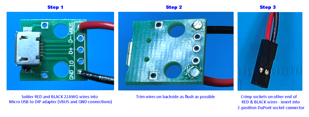
- Step 1: Strip about 1/8″ / 3mm from about a 5″ / 127mm long piece of RED 22AWG wire and insert that end in the VBUS hole on the Micro USB to DIP adapter. Strip about 1/8″ / 3mm from a 5″ / 127mm long piece of BLACK 22AWG wire and insert that end in the GND hole on the Micro USB to DIP adapter.
- Step 2: Flip the Micro USB to DIP adapter board over, solder the BLACK and RED wires, and trim the wire on the back side as flush as possible with the board (it doesn't have to be perfectly flat) as shown in Step 2 of the picture.
- Step 3: Strip about 0.1″ (2mm) from the other ends of the two wires. On each wire, crimp a female crimp socket and insert them both into a 2-position DuPont socket connector as shown in Step 3 of the picture.
Step 13: Construct Power Button Assembly
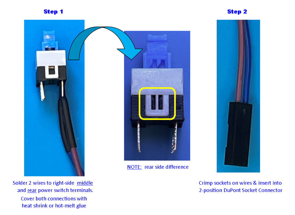
This one's also a pretty quick and easy one. The power button is used to signal power ON and OFF events to the Safe Shutdown control circuit. To assemble:
- Step 1: Strip about 1/8″ / 3mm from two signal wires (I used PURPLE and BLUE) about 8″ / 203mm long. Solder these signal wires onto a set of the Normally Open (NO) contacts of the push ON/push OFF power button (you can test this with a multimeter on a continuity or resistance setting – the continuity setting should beep or the resistance setting should show very low Ohms on the NO contacts with the button pushed ON). For the switch I purchased, I used the rear right two contacts with the switch positioned as shown in Step 1 of the picture. After soldering, install heat shrink tubing or hot-melt glue over the contacts to prevent accidental shorting and breakage of the wires due to excessive bending at the solder joints. .
- Step 2: Strip about 0.1″ / 2mm from the other ends of the two wires. On each wire , crimp a female crimp socket and insert them both into a 2-position DuPont socket connector as shown in Step 2 of the picture.
Step 14: Construct VCR Assembly
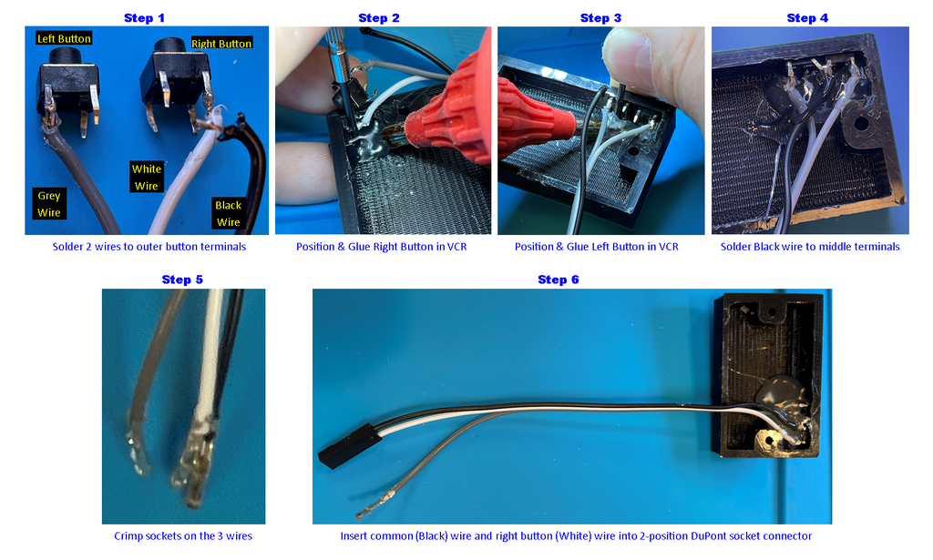
The VCR assembly sits on top of the TV. It uses the two small 6mm x 6mm x 6mm momentary buttons that implement the pause/play, rewind, next video, and channel change features. There are four pins on each of the buttons; two on one side are always shorted together and the other two on the other side are always shorted together. When you press the button, the two sets of pins are connected together. Use a multimeter’s continuity or resistance setting to determine which pins are NOT connected together when the button is NOT pressed – these are the ones we want to use). NOTE: you may have to use a small round file in the 3D printed VCR button holes to insure free movement of the buttons. Test position and operation of the buttons before gluing. To build the VCR assembly:
- Step 1: Get three pieces of signal wire each about 6” / 152mm long (I used GREY, WHITE, and BLACK). Strip about 1/16” / 2mm from the WHITE and GREY wires. Solder these two wires to the top outer pins of the two buttons as shown in Step 1 of the picture (NOTE: the top inner pins are the ones that should NOT be connected to the top outer pins with the wires until the buttons are pressed).
- Step 2: Position the right button (the one with the WHITE wire) in the outermost button hole of the 3D printed VCR and use hot-melt glue to glue it in place as shown in Step 2 of the picture. Only cover the lower terminals with the hot-melt glue – do not glue the top terminals yet. Use something like a small screwdriver to hold the button in place while gluing (you may have to hold it for a few minutes while the glue cools and hardens).
- Step 3: Position the left button (the one with the GREY wire) in the innermost button hole of the 3D printed VCR and use hot-melt glue to glue it in place as shown in Step 3 of the picture. Only cover the lower terminals with the hot-melt glue – do not glue the top terminals yet. Use something like a small screwdriver to hold the button in place while gluing (you may have to hold it for a few minutes while the glue cools and hardens).
- Step 4: Bend the two top-inner terminals of the buttons so that they touch. Strip about 1/16” / 2mm from the BLACK wire. The BLACK wire is the GND (or common) for the left and right buttons. Solder the BLACK wire to the two top-inner terminals of the two buttons. Apply hot-melt glue on the top terminals and wires (but not too much – we only want to protect the terminals and wires from bending at the solder joints – we do not want the hot-melt glue to extend past the open bottom of the 3D printed VCR.
- Step 5: Strip about 0.1” / 3mm from the other end of the three wires and crimp on a female crimp socket on each of them.
- Step 6: Insert the BLACK (common) and WHITE (right button) crimp sockets into a 2-position DuPont socket connector as shown in Step 6 of the picture. NOTE: The crimp socket on the GREY (left button) wire will remain loose right now – it will later be inserted in the middle position of the 3-position DuPont socket connector of the audio amplifier.
That's it – we're done with this assembly.
Step 15: Prepare Raspberry Pi Hardware
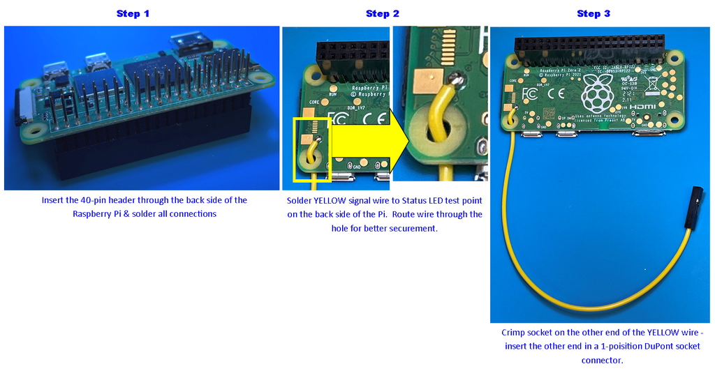
The Raspberry Pi electromechanical assembly is also pretty quick and easy. Basically, we're soldering on a 40-pin header with extended pins (the extended pins are used to connect to the DuPont connectors) and a single wire to make the Status LED signal of the Pi available to the Safe Shutdown circuit. Without further delay, let’s get going…
- Step 1: Insert the 2×20 extended pin socket header through the back side of the Raspberry Pi Zero 2 W’s circuit board and solder in place as shown in Step 1 of the picture. Keep the solder at the bottom of the extended pins to prevent interfering with connecting DuPont socket connectors. If you accidentally get some solder blobs on the upper part of extended pins 2, 4, 6, 20, 22, 23, 35, 37, or 39, use some solder wick to remove as much of it as you can. The other pins do not matter so much unless you want to use those signals for your own purposes.
- Step 2:: Strip about 0.1” / 3mm from a single signal wire about 6” long (I used YELLOW). Thread this signal wire through the lower left mounting hole of the Pi and solder the stripped end to the Status LED test point as shown in Step 2 of the picture. It is also a good idea to apply some hot-melt glue on the YELLOW wire at the mounting hole to help prevent the Status LED test point pad from accidentally being pulled off during handling.
- Step 3: Strip about 0.1” / 3mm from the other end of the YELLOW wire and crimp on a female crimp socket. Insert this crimp socket into a 1-position DuPont socket connector as shown in Step 3 of the picture.
All done with this section – see, not too bad.
Step 16: Set Up the Raspberry Pi: Installing the OS on the Micro SD Card
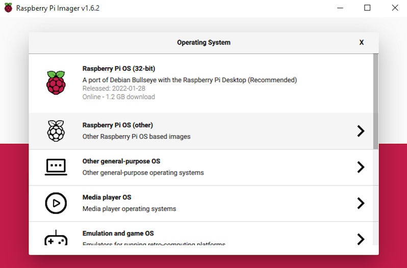
Insert the 64GB micro SD Card in a computer. Then, use the Raspberry Pi Imager to install the headless version of the Operating System on the 64GB SD card. Select “Operating System” -> “Raspberry Pi OS (other)” -> “Raspberry Pi OS Lite (Legacy)”. Be sure to select the “Buster” version and not the “Bullseye” version as OMX Player is not supported in newer versions of the Raspberry Pi OS.
Then, in the Raspberry Pi Imager, click on the “Storage” button, select the SD card option, then click “Write“. Click “Yes” on the pop-up prompt to overwrite the data on the SD card.
Once the process completes, you may need to remove and re-insert the micro SD card back into the computer for it to recognize the boot partition on it.
In a text editor such as Notepad, Notepad++, or Wordpad, create a new file and paste the following text into it:
country=US
ctrl_interface=DIR=/var/run/wpa_supplicant GROUP=netdev
update_config=1

network={
  ssid="YOUR NETWORK NAME"
  psk="YOUR NETWORK PASSWORD"
}
Change “YOUR NETWORK NAME” to your Wifi's SSID name (keep the quotes) and “YOUR NETWORK PASSWORD” to your WiFi's password (again, keep the quotes). Save this file to the SD Card's “Boot” partition as:
wpa_supplicant.conf
NOTE: The Raspian OS will use this file to set up WiFi access during its first boot. After this first boot on the raspberry pi, the wpa_supplicant.conf file will be moved from the root directory on the boot partition to the “/etc/wpa_supplicant/” directory. So, if you need to change the network ssid and/or password later, simply edit the ssid and psk parameters in the wpa_supplicant.conf file located in the /etc/wpa_supplicant/ directory on the Pi and reboot.
Then, in the text editor, create another new file. Type no text and simply save this empty file to the SD Card's “Boot” partition as:
ssh
This will enable the ssh service at bootup.
Once the process is complete, eject the SD card from the computer and install it into the Raspberry Pi.
Step 17: Set Up the Raspberry Pi: Connect Monitor and Power
Connect an HDMI monitor and power source to the Raspberry Pi as shown in the picture above. At this time, the IP address assigned to the Pi should scroll up on the screen, take a note and jot it down. You should now be able to log into the Raspberry Pi remotely on a computer logged into the same network as the Pi.
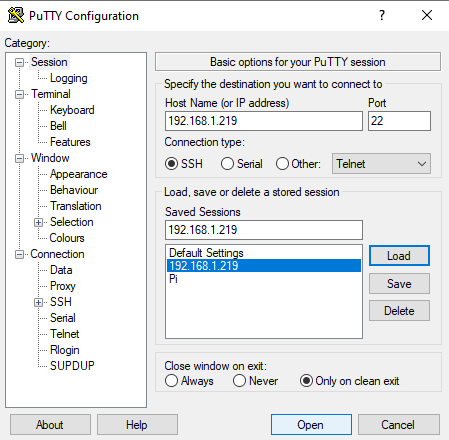
Using a terminal program, such as Putty, establish a SSH session with the Raspberry Pi at the IP address you noted on the HDMI screen connected to the Pi as it booted (reference example picture above). Alternately, in Windows, you can type the following at a system command prompt to establish an SSH session with the Pi:
ssh raspberrypi.local -l pi
If you didn't see the IP address or if it changed, you can type “ping raspberrypi” at a system command prompt on your computer to see what IP address is returned.
Once the SSH session is established, you will need to enter the login credentials of the Raspberry Pi. The default user is “pi” and the password is “raspberry” as shown below:
login as: pi
[email protected]'s password:
Linux raspberrypi 5.10.63-v7+ #1496 SMP Wed Dec 1 15:58:11 GMT 2021 armv7l

The programs included with the Debian GNU/Linux system are free software;
the exact distribution terms for each program are described in the
individual files in /usr/share/doc/*/copyright.

Debian GNU/Linux comes with ABSOLUTELY NO WARRANTY, to the extent
permitted by applicable law.
Last login: Mon Feb 14 05:05:40 2022

SSH is enabled and the default password for the 'pi' user has not been changed.
This is a security risk - please login as the 'pi' user and type 'passwd' to set a new password.

pi@raspberrypi:~ $
Now, we need to update the OS. In the terminal, type:
sudo apt-get update
After that finishes, type:
sudo apt-get upgrade
You may get a prompt asking, “Do you want to continue? [Y/n]”. Type Y and hit <ENTER>
Enabling USB Drive Support:
A USB drive will later be needed to copy your video files over to the Pi's SD card. We will need to install a couple of packages to allow easy mounting and dismounting of a USB drive to the Pi with the following commands:
sudo apt-get install usbmount
Again, you may get a prompt asking, “Do you want to continue? [Y/n]”. Type Y and hit <ENTER>
sudo apt-get install eject
Now, we will finish up USB drive support by editing the systemd-udevd.service file. To do this, type the following command:
sudo nano /lib/systemd/system/systemd-udevd.service
Scroll down to where it says:
PrivateMounts=yes
Change it to:
PrivateMounts=no
Save the file by typing Ctrl-o, hit <ENTER>, then exit the editor by typing Ctrl-x
Configure Auto Log-In at Boot
We need to make sure the Raspberry Pi just boots up without being stopped to Login on the 3.5″ LCD. To do this, enter the following in the terminal at a command prompt:
sudo raspi-config
- Select “1 System Options“
- Select “S5 Boot / Auto Login“
- Select “B2 Console Autologin“
- Select “OK“
- Select “Finish“
The system will ask you, “Would you like to reboot now?”
Select “Yes“.
If you accidentally select “No”, no worries – you can still reboot by entering the following command:
sudo reboot -h now
Install 3.5″ LCD Graphics Drivers:
First, we will need to install the git package. Git allows you to clone files and file structures from github. This is needed to install the 3.5″ LCD graphics drivers. To install the git package, type the following command:
sudo apt-get install git
You may get a prompt asking, “Do you want to continue? [Y/n]”. Type Y and hit <ENTER>
Instructions come with with the iUniker 3.5″ LCD that tell you how to install the display drivers. You should follow those instructions. For the one I got, the instructions state to type the following commands:
cd ~/
git clone https://github.com/tianyoujian/MZDPI.git
cd MZDPI/mzp351hv00br
sudo chmod +x mzdpi-hvga-autoinstall
sudo ./mzdpi-hvga-autoinstall
Most likely, you will have encountered errors on that last command due to several package dependencies not being installed. You can install these dependencies manually or type the following command to install all the dependencies from the last command:
sudo apt --fix-broken install
This will install several packages. You may get prompts asking “Do you want to continue? [Y/n]”. Type Y and hit <ENTER> for each of these.
Once these package installations all complete, type the following command again:
sudo ./mzdpi-hvga-autoinstall
This time, this command should complete successfully. At this point, if you reboot, system video will be sent to the 3.5″ LCD (if attached) – the HDMI port will not work. No worries though – your SSH session “look” will not change.
NOTE: To re-enable the HDMI port, you can edit the config.txt file using the following command:
sudo nano /boot/config.txt
scroll to “include mzp351hv00br.txt” and comment it out by putting a “#” in front of it. This will look like, “#include mzp351hv00br.txt“.
Save the file by typing Ctrl-o, then exit the editor by typing Ctrl-x
The next time you reboot, the video will be sent back out the HDMI connector.
To re-enable output to the 3.5″ LCD, just re-edit the config.txt file again and remove the “#” so that you have “include mzp351hv00br.txt” again. Save and exit. The next time you reboot, the video will be sent to the 3.5″ LCD.
Enable Audio Output:
Some of the GPIO pins on the Raspberry Pi Zero 2 have special alternate functions. One of those functions happens to be PWM audio output on pins 18 and 19. This project utilizes only the audio output on GPIO 19. So, to enable the PWM audio output on pin 19, we need to first edit the config.txt file located in the /boot/ directory again. To do this, type the following command:
sudo nano /boot/config.txt
Scroll to the bottom of this file and add the following text:
dtparam=audio=on
dtoverlay=audremap,enable_jack,pins_19
Save the file by typing Ctrl-o, then exit the editor by typing Ctrl-x
Next, we need to edit the rc.local file by typing the following command:
sudo nano /etc/rc.local
Add the following text towards the bottom, but before Exit 0.
sudo raspi-gpio set 19 op a5
This enables alternate function 5 (PWM output) on the GPIO19 pin.
Save the file by typing Ctrl-o, then exit the editor by typing Ctrl-x.
Simplify Boot Text:
For this next step, we will minimize the amount of boot text spewed out during the power ON process. We will also change the font size displayed on the screen so that channel and selection text will be clearly visible on the small display.
To start, type the following command:
sudo nano /boot/cmdline.txt
This file consists of a single line of a long list of parameters. scroll across and locate where it says console=tty1. Change just this text to:
console=tty3
continue scrolling until you locate fsck.repair=yes. Remove this text.
Now, go to the end of this line and add the following text:
consoleblank=0 logo.nologo quiet splash
Save the file by typing Ctrl-o, then exit the editor by typing Ctrl-x.
Increase System Font Size:
Now, we need to increase the system font size so that it is easier to see on the 3.5″ screen (needed for the program message outputs from the player.py python script). To increase the font size, type the following command:
sudo dpkg-reconfigure console-setup
Select UTF-8 -> Guess Optimal Character Set -> Terminus -> 16X32
NOTE: To revert back to the original font, type the above command again, but select:
UTF-8 -> Guess Optimal Character Set -> Do not change the boot/kernel font
Install OMXPlayer:
The omxplayer is the application used to actually play the videos. There are two pieces to install the omxplayer, the application itself and the omxplayer wrapper that allows our python script to interface to the omxplayer application.
So, the first step is to install the omxplayer application. To do this, enter the following command:
sudo apt-get install omxplayer
You may get a prompt asking, “Do you want to continue? [Y/n]”. Type Y and hit <ENTER>
To install the omxplayer wrapper and its dependencies, follow these steps in order (NOTE: some of these packages may already be installed via previous steps – but, follow these steps just to be sure):
sudo apt-get install -y libdbus-1-3
sudo apt-get install -y libdbus-1-dev
sudo apt-get install python-pip
sudo apt-get install python-dev
sudo apt-get install libglib2.0-dev
sudo pip2 install omxplayer-wrapper
sudo pip install --upgrade --no-deps --force-reinstall pathlib
For some of these steps, you may get a prompt asking, “Do you want to continue? [Y/n]”. Type Y and hit <ENTER>
Set Up Directory Structure:
Now, we need to set up the directory structure for “The Simpsons TV”. To do this, execute the following commands:
sudo mkdir ~/simpsonstv
sudo mkdir ~/simpsonstv/videos
sudo mkdir ~/simpsonstv/videos/"The Simpsons"
The directories under ~/simpsonstv/videos/ are considered to be “Channels“. So, continue using the sudo mkdir ~/simpsonstv/videos/<Channel> command for as many channels as you want. For example, on mine, I made directories(Channels) for Horror, Comedy, Action, Animated, Family, and Sci-Fi. When changing a “channel” in the python script, it is actually just switching to a different subdirectory. NOTE: If you want to make a directory with a space in it, be sure to put it in quotes just like was done in the command shown above making “The Simpsons” directory.
Creating player.py Python script:
We now are ready to create the python script that will run everything. It will be named “player.py” to be consistent with the original project. To create this python script, enter the following command (or, you can download the player.py file in this section and copy it to the ~/simpsonstv/ directory on the Pi):
sudo nano ~/simpsonstv/player.py
Then copy/paste the following text into the nano text editor (paste in the nano editor by copying the text below, then selecting your terminal window, then right-clicking your mouse.):
######################################################################################
# player.py
# Version:   1.0
# Author:    D.J. Hatfield
# Date:      2/21/2022
# Device:    Raspberry Pi Zero 2 W
# Purpose:   At startup, this script will start playing videos in the first subdirectory
#            under the "~/simpsonstv/videos/" specified by the "Directories" string array.
#            The next video in the same directory will automatically be played once the
#            existing video has completed playing.  All videos will be played in the current
#            specified directory and will loop around again once all are complete.
#
#
#            It also utilizes two "VCR" button inputs to implement the following features:
#             Right Button (GPIO 25):
#                -Quickly tap the button to select the next video in the current directory
#                -Press and hold the button for > 2 seconds to select the next "Channel"
#                 ("Channels" are just subdirectories under the ~/simpsonstv/videos/ directory and
#                  are specified in the "Directories" string array)
#             Left Button (GPIO 26):
#                -Quckly tap the button to pause or play the current video
#                -Press and hold the button for > 1 second to rewind current video by 10 seconds
#                 (continue holding to keep rewinding additional 10 seconds every second the button
#                  is pressed)
#             Press and hold BOTH the Right and Left buttons for > 5 seconds to shutdown the
#             OMXPlayer and exit this Python script and return to a command prompt.  NOTE: once
#             this Python script is terminated, the safe shutdown functionality will not work.
#             You will need to either restart this Python script to re-enable this functionality
#             or issue a "sudo shutdown now" command from a command prompt to safely shutdown the
#             Pi.
#
#             Additionally, this script monitors the Shutdown input (GPIO 11).  If this pin
#             is asserted (active LOW) for > 50mS, the Pi will be Shut down.
###########################################################################################


from omxplayer.player import OMXPlayer
from pathlib import Path
import os
import RPi.GPIO as GPIO
#import time as time_ - makes sure we don't override time
import time as time_
GPIO.setmode(GPIO.BCM)
GPIO.setup(26, GPIO.IN, pull_up_down=GPIO.PUD_UP) #Set GPIO 26 as input with pull-up
GPIO.setup(25, GPIO.IN, pull_up_down=GPIO.PUD_UP) #Set GPIO 25 as input with pull-up
GPIO.setup(11, GPIO.IN, pull_up_down=GPIO.PUD_UP) #Set GPIO 11 as input with pull-up


# Add/change your video subdirectories in the Directories string array
# These are the "Channels"
Directories = ["The Simpsons", "Horror", "Action", "Comedies", "Animated", "Sci-Fi"]


#     <<<ROUTINES>>>
#-----------------------------------------------------------------------------------------------------------------
# millis(): Returns the number of milliseconds elapsed since power up.
def millis():
    return int(round(time_.time() * 1000))
#-----------------------------------------------------------------------------------------------------------------
# displayDirectoryVideo():  Displays the currently selected Video and Channel on the LCD
#                           Returns nothing
def displayDirectoryVideo():
    #Must specify "global" variables - otherwise, the routine would create its own unique copy
    # of these variables when they are used.
    global Root_Path
    global Current_Directory
    global Current_Video
    global VIDEO_PATH
    global PlayTimer
    global playNew
    os.system("clear")  #clear the LCD screen
    Current_Video = videos[Video_Pointer]  #Set current video to that specified by the Video_Pointer
    VIDEO_PATH = Path(Root_Path + Current_Directory + "/" + Current_Video)
    print("")
    print("")
    print("")
    print("  Channel: " + Current_Directory)  #Print the "Channel" (directory) on the LCD screen
    print("  " + Current_Video[0:len(Current_Video)-4])  #Print the video selected on the LCD screen
    PlayTimer = millis()
    playNew = True  #Trigger starting the play of the new video in 1.5 seconds
#-----------------------------------------------------------------------------------------------------------------
# nextVideo(): Select the next video by incrementing the Video_Pointer;  Loops around once the end is reached
#              Returns nothing
def nextVideo():
    #Must specify "global" variables - otherwise, the routine would create its own unique copy
    # of these variables when they are used.
    global Video_Pointer
    global videos
    global manualSelect
    global player
    manualSelect = True  #Set the flag to indicate the next video was manually selected
    player.quit()        #Stop the currently playing video - this kills the current OMXPlayer instance
    Video_Pointer += 1   # Increment Video_Pointer
    if(Video_Pointer > (len(videos)-1)):
      Video_Pointer = 0  #Loop Video_Pointer back around once end of videos is reached
    displayDirectoryVideo() #Display Channel and Selected Video on the LCD screen


#-----------------------------------------------------------------------------------------------------------------
# getVideos(): Update the videos string array with a list of videos in the currently selected channel (directory)
#              Returns nothing
def getVideos():
    #Must specify "global" variables - otherwise, the routine would create its own unique copy
    # of these variables when they are used.
    global videos
    global Current_Directory
    global Root_Path
    videos = []  #Clear out the videos string array
    for file in os.listdir(Root_Path + Current_Directory):  #Cycle through all files in the current directory and
        if file.lower().endswith('.mp4'):                   #add to videos string array if it is an mp4 video file
            videos.append(file)
    videos.sort() #Rearrange the videos in the videos array in alpha-numerical order


#-----------------------------------------------------------------------------------------------------------------
# switchDirectory(): Select the next channel (directory) in the Directories string array - also point to the first
#                    video in this newly selected channel.
#                    Returns nothing
def switchDirectory():
    #Must specify "global" variables - otherwise, the routine would create its own unique copy
    # of these variables when they are used.
    global Video_Pointer
    global Directory_Pointer
    global Current_Directory
    global Directories
    global manualSelect
    global player
    manualSelect=True   #Set the flag to indicate the next video was manually selected
    player.quit()       #Stop the currently playing video - this kills the current OMXPlayer instance
    Video_Pointer = 0   #Set video pointer to the first video in the newly specified channel
    Directory_Pointer +=1 #Increment the Channel Pointer
    if(Directory_Pointer > (len(Directories)-1)):
      Directory_Pointer = 0  #Loop the Channel pointer back around once end of channels is reached
    Current_Directory = Directories[Directory_Pointer]  #Set current channel specified by the Directory_Pointer
    getVideos()         #Identify all videos in the newly specified channel (directory)
    displayDirectoryVideo()  #Display Channel and Selected Video on the LCD screen
#-----------------------------------------------------------------------------------------------------------------
# autoPlayNext(): Executed when an instance of OMXPlayer exits.  It automatically starts playing the next video in
#                 the current channel if the last video played to completion.  It will not try to play a video if
#                 OMXPlayer was shutdown by the user manually (i.e. selecting through videos for the next video).
#                 In the case of a manual video selection, the video will be played in the main loop.
#                 Returns nothing
def autoPlayNext(code):
   #Must specify "global" variables - otherwise, the routine would create its own unique copy
   # of these variables when they are used.
   global Video_Pointer
   global videos
   global manualSelect
   global Video_Pointer
   if (manualSelect == True):  #If this routine was entered by the user manually selecting the next video,
     manualSelect = False      # clear the manualSelect flag and,
     return                    # return doing nothing else - the main loop will handle manual select operations
   Video_Pointer +=1 # If this routine was entered due to a video completing playback, increment the Video_Pointer
   if(Video_Pointer > (len(videos)-1)):  #Loop the video pointer back around once the end of videos is reached
     Video_Pointer = 0
   displayDirectoryVideo()     #Display Channel and Selected Video on the LCD screen


#--------------------------------------------------------------
#     <<<INITIALIZATION>>>     Executed only once at script start
os.system("clear")             #Clear the LCD screen
Video_Pointer = 0              #Set Video Pointer to point to the first video file in the current channel
oneShotNextVideo = False       #Controls incrementing video pointer only ONCE per right button press
oneShotNextDirectory = False   #Controls incrementing directory pointer only ONCE per extended right button press
manualSelect = False           #Indicates manual video select vs automatic selection of new video file
PlayTimer = 0                  #Delays playing next video (allows user to read Channel/Video selection on LCD
Root_Path = "/home/pi/simpsonstv/videos/"  #Path to this application's video channels(subdirectories)
Directory_Pointer = 0          #Set Channel (directory) pointer to first entry
Current_Directory = Directories[0] #Point current Channel to first directory in the Directories string array
getVideos()                    #populate videos string array with all video files located in the current channel
Current_Video = videos[0]      #Point current video to first video in the videos string array
VIDEO_PATH = Path(Root_Path + Current_Directory + "/" + Current_Video) #Set video path
player = OMXPlayer(VIDEO_PATH) #Start playing video specified by the video path
player.exitEvent += lambda _, exit_code: autoPlayNext(exit_code) #Set OMXPlayer exit event handler to call the
                                                                 # autoPlayNext() routine when OMXPlayer exits
Button1Timer = millis()        #Used to debounce VCR right button for select next video indication
Button2Timer = millis()        #Used to debounce VCR left button for select pause/play indication
ShutDownTimer = millis()       #Used to debounce Shutdown signal from the safe shutdown circuit
ExitPythonTimer = millis()     #Used to debounce the long press of BOTH left & right buttons to exit python script
seekTimer = millis()           #Used to debounce left button rewind long press
seekToggle = True              #Used to pulse a 10 second rewind for every second the left button is pressed
playNew = False                #When true, triggers playing a new video 1.5 seconds after a new video selection.
oneShotPlayPause = False       #Used to control executing a play or pause command only ONCE per left button press
skipPause = False              #Prevents executing a play/pause command during long (rewind) press of left button


#----------------------------------------------------------------------------------------------------------------
#     <<<MAIN>>>     Main program loop - continuously executes
while (True):


   input1 = GPIO.input(25)  #Read VCR right button input
   input2 = GPIO.input(26)  #Read VCR left button input
   ShutItDown = GPIO.input(11)  #Read Shutdown signal input
   #Check GPIO 25 and debounce high and low going pulses to see if
   #commanded to switch to next video in the current directory
   #or if commanded to go to the next channel (directory) if button pressed longer than 2 seconds
   if((input1 == True) and (oneShotNextVideo == False)):
     Button1Timer = millis()
     oneShotNextDirectory = False
   #Debounce right button (GPIO 25) going to the active state (LOW) for 100mS to select next video
   if((input1 == False)):
     temp = millis()
     if((temp - Button1Timer) >= 100):
        PlayTimer = millis()
        if(oneShotNextVideo == False):
          oneShotNextVideo = True
          nextVideo()
        oneShotCheckLow = True
     #Continue checking for button press > 2 seconds for change channel (directory)
     if((temp - Button1Timer) >= 2000):
        if(oneShotNextDirectory == False):
          switchDirectory()
          oneShotNextDirectory = True


   #Debounce right button (GPIO 25) going to the inactive state (HIGH) for 50mS
   if((input1 == True) and (oneShotNextVideo == True) and (oneShotCheckLow == True)):
      oneShotCheckLow = False
      Button1Timer = millis()
   if((input1 == True) and (oneShotNextVideo == True)):
      temp = millis()
      if((temp - Button1Timer) >= 50):
        oneShotNextVideo = False
   #-------------------------------------------------------------
   #Check GPIO 26 and debounce high and low going pulses to see if
   #commanded to switch to pause or rewind 10 seconds if pressed longer than 1 second
   if((input2 == True) and (oneShotPlayPause == False)):
     Button2Timer = millis()
     skipPause = False
   #Debounce left button (GPIO 26) going to the active state (LOW) for 100mS to toggle pause/play
   if((input2 == False)):
     temp = millis()
     if((temp - Button2Timer) >= 100):
       if((oneShotPlayPause == False) and (skipPause == False)):
         oneShotPlayPause = True
     #Continue checking for button press > 1 second for rewind
     if((temp - Button2Timer) >= 1000):
       if(seekToggle == True):
         try:                        #Implement exception handler (try: and except:) - prevents python script from
                                     # crashing if exception occurs during (try:) code
           player.seek(-10)          #Rewind video 10 seconds - causes exception if OMXPlayer has been terminated
           seekToggle = False
           seekTimer = millis()
           oneShotPlayPause = False
           skipPause = True
         except Exception as e:      #Exception handler - executes if exception occurs during above try:
           Nothing = 0               #  Exception code:does nothing-just catches exception/prevents Python crash
       #Continue rewinding 10 seconds for every 1 second the left button is pressed
       if((temp - seekTimer) >= 1000):
         seekToggle = True
         seekTimer = millis()


   #Debounce left button (GPIO 26) going to the inactive state (HIGH) for 50mS
   if((input2 == True) and (oneShotPlayPause == True)):
      temp = millis()
      if((temp - Button2Timer) >= 50):
        try:                         #Implement exception handler (try: and except:) - prevents python script from
                                     # crashing if exception occurs during (try:) code
          player.play_pause()        #Toggle video play/pause - causes exception if OMXPlayer has been terminated
          oneShotPlayPause = False
        except Exception as e:       #Exception handler - executes if exception occurs during above try:
          Nothing = 0                #  Exception code:does nothing-just catches exception/prevents Python crash


   #-------------------------------------------------------------
   #Check for special case of both VCR buttons pressed > 5 seconds (command to exit player.py Python script)
   if ((input1 == False) and (input2 == False)):
     temp = millis()
     if ((temp - ExitPythonTimer) >= 5000):
       player.quit()                 #Shut down OMXPlayer
       print("Exiting Python script")
       quit()                        #Exit player.py Python script
   else:
     ExitPythonTimer = millis()


   #-------------------------------------------------------------
   #Check GPIO pin 11 for signal to safetly shutdown Pi (active low)
   #  this signal is only debounced on assertion for 50mS
   temp = millis()
   if ((ShutItDown == False) and ((temp - ShutDownTimer) >= 50)):
     os.system("clear")              #Clear the LCD screen
     print("")
     print("")
     print("  Shutting Down...")     #Print "Shutting Down..." message on the LCD screen
     os.system("sudo shutdown -h now") #Shut down the Raspberry Pi - the safe shutdown circuit will monitor the
                                       # status LED signal and remove power once activity ceases
   if (ShutItDown == True):          #Reset ShutDown timer if ShutItDown signal deasserts before timer times out
     ShutDownTimer = millis()


   #-------------------------------------------------------------
   #Play next selection 1.5 seconds after last command to change video or directory
   #  This allows enough time for a user to read the channel (directory) and
   #  new video selected on the screen
   #  This is controlled by the playNew boolean variable.  When playNew is set, it
   #  triggers playing the new video 1.5 seconds later
   temp = millis()
   if((temp - PlayTimer) >= 1500 and (playNew == True)):
     player=OMXPlayer(VIDEO_PATH)   #Start playing video specified by the video path
     player.exitEvent = lambda _, exit_code: autoPlayNext(exit_code) #Set OMXPlayer exit event handler to call the
                                                                     # autoPlayNext() routine when OMXPlayer exits
     playNew = False                #Reset the playNew flag
     manualSelect = False           #Reset the manualSelect flag (indicates automatic play unless changed by user)
Before you save, you should modify line 51 of the python code with your directories (“channels”). Line 51 above defines a string array called Directories. This line of code is explicitly:
Directories = ["The Simpsons", "Horror", "Action", "Comedies", "Animated", "Sci-Fi"]
Change the entries to match the sub-directories you created in the ~/simpsonstv/videos/ directory. The order in this string array determines the order that the “channels” will sequence through when you press the “Next Channel” function on the VCR. Feel free to add or delete “channels”.
When you are done editing, save the file by typing Ctrl-o. Give it the filename “player.py“, then exit the editor by typing Ctrl-x.
Almost there! All that is left on the software side of things is to copy your video files into their “Channels” and configure the system to automatically start running the player.py python script at startup.
Step 18: Copying Video Files Into Channels
On your computer, copy your legally-owned video files you generated onto a USB drive. The ideal format for these videos is .mp4 with a screen resolution of 480 pixels wide by 320 pixels tall (3:2 format). Although, 4:3 format videos play well on the screen with very little black banding at the top and bottom of the screen. Handbrake is an excellent, free program that you can use to re-format your videos into the 480 x 320 format. Also, be sure your videos are in the MP4 format.
For this step, I'm assuming you have videos already generated and ready to be copied onto your “Simpsons TV”.
- So, first copy the videos to a USB drive on your computer.
- Then, eject the USB drive from the computer.
- Insert the USB drive into your Raspberry Pi (NOTE: you will likely need a full-size USB-A to USB-micro-B adapter)
- The USB drive will be automatically mounted to the /media/usb/ directory.
To copy your video files from the USB drive, enter the following command:
cp /media/usb/* ~/simpsonstv/videos/<directory>/
where /media/usb/* is the source directory and wildcard for all files and ~/simpsonstv/videos/<directory> is the “Channel” subdirectory to which you want to copy the videos (replace <directory> with the name of the subdirectory). Just a reminder, be sure to use quotes around the subdirectory name or filename if it has one or more spaces in it. Modify the directory structure as needed to match your source and destination directories.
Once you are done copying files from the USB drive, you can eject it by entering the following command:
sudo eject /dev/sda1
To see how much memory space you have left on your SD card, enter the following command:
df -h
This shows the amount of free space in /dev/root is available to use for videos.
The last software configuration task is to configure the system to start the player.py python script at startup.
Configuring Automatic Startup of player.py
I'm going to diverge from Brandon's implementation a bit more here. Brandon implemented a couple of services at boot time to start up and run his python scripts. This does not work well for my implementation as I want to print Channel and Video selection text on the LCD screen when a user presses the “Next Video” button or changes “Channels”. If I used a service to start my python script, it would not show any text I printed out to the screen. This has to do with when the python.py script is started. If it is started during system initialization (as is done with the services method), then it does not get access to the screen.
To solve this problem, I used the .bashrc file to start up my player.py python script. This is easy to do. Simply modify the .bashrc file by entering the following command:
sudo nano ~/.bashrc
scroll to the end of the file and enter the following on the last line:
sudo python ~/simpsonstv/player.py
Save the file by typing Ctrl-o, hit <ENTER>, then exit the editor by typing Ctrl-x.
Shutdown the Pi by typing the following command:
sudo shutdown now
Remove all power and cables from the Raspberry Pi once the activity LED is fully OFF and no longer blinking.
Whew! You've done a lot! – go take a break, get a snack, save the planet…We'll still be here when you get back. The final steps will be gluing and plugging everything together.
Step 19: Finish Assembly (Glue Time!)
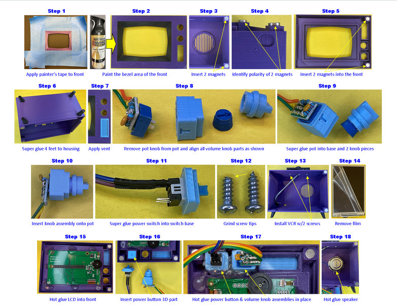
We’re now coming down the home stretch! All that is left is to assemble the 3D printed parts, mount the assemblies you’ve made, and connect all the electrical connections. There are a lot of steps, so let’s get going…
- Step 1: If you’re going to spray paint the bezel area of the TV front (like I did), apply painter’s tape to the TV front to mask off all the areas you don’t want the paint to go. Wrap the painter’s tape around the sides to prevent overspray from depositing there.
- Step 2: Paint the bezel area of the TV front. I used a gloss black spray paint compatible with plastic (I used Rustoleum Universal) because I’m better with spray paint than I am painting with a brush. Plus, I couldn’t find the spray paint in Dioxazine Purple (or similar color) that Brandon specified in his build. Remove the painter’s tape and, while the paint is still soft, use cotton swabs wetted with isopropyl alcohol to clean any overspray or leakage under the painter’s tape around the outer bezel edges.
- Step 3: Press fit two of the 1/4″ x 1/16” magnets into the TV housing as shown in Step 3 of the first assembly picture. If the holes are too tight for the magnets to fit, use a small round file to ream out the holes to fit. If the magnets fit too loosely, use a small amount of super glue to affix the magnets in the holes.
- Step 4: Identify the magnetic pole polarity of the other two 1/4″ x 1/16” magnets by placing them on the first two you installed in the TV housing. Since these will be used to hold the TV front onto the TV housing, they need to attract one another and not repel.
- Step 5: Insert the two magnets from Step 4 into the TV front (noting the proper orientation for attraction to the other magnets) as shown in Step 5 of the first assembly picture. Use the same techniques outlined in Step 3 if the magnets do not quite fit right or securely.
- Step 6: Using just a drop of super glue for each TV foot, glue the four TV feet into the recesses on the bottom of the TV housing. Test fit each TV foot before gluing. You will likely need to use a small flat file to file around the edges of each TV foot to get it to fit in the recess due to the first 3D-printed layer spreading out a bit. Use a small round file if you need to clean up any of the recesses on the TV housing. Note the proper orientation of each TV foot in Step 6 of the first assembly picture.
- Step 7: Use a sparing amount of super glue to glue in the front grille into the TV front. Test fit first before gluing. You may need to use a small flat file on the front grille sides to insure a proper fit.
- Step 8: Remove the potentiometer (pot) knob from the audio circuit by prying it off with a small screwdriver. Align the pot of the audio circuit assembly with the volume knob base (Note the orientation of the volume knob base relative to the pot position as the shaft of the pot is not symmetrically positioned in the body of the pot – the “T” on the volume knob base marks the TOP).
- Step 9: Using a sparing amount of super glue, affix the pot into the volume knob base (be careful and do not use too much glue as capillary action could cause the glue to flow into the front of the pot, which will ruin it – apply only to the sides of the inside of the volume knob base). Again, test the fit before gluing and note the proper orientation of the pot shaft in the volume knob base – it should be centered in the hole. Also, glue the volume knob on the pot knob with a small amount of super glue. You will likely need to use small round and flat files to clean up the insertion points of the 3D prints so that the pot and its knob will fit properly with the 3D printed parts.
- Step 10: Insert the assembled volume knob onto the pot shaft as shown in Step 10 of the first assembly picture.
- Step 11: Use a very small amount of super glue applied only to the inner sides of the power button base to affix the power button as shown in Step 11 of the first assembly picture. The switch is particularly prone to super glue flowing into it via capillary action, which will destroy it – so, again, a very small amount of super glue. Test fit before gluing and file the power button base as needed for proper fit. Note the switch orientation.
- Step 12: File or grind away the tips of the two #6 x 3/8” long machine screws to prevent them from causing a small bump in the VCR when they are screwed in.
- Step 13: Route the three wires of the VCR assembly through the square hole on the top of the TV housing. Use the two #6 x 3/8” long machine screws to attach the VCR assembly to the TV housing (don’t over tighten).
- Step 14: Remove the protective film from the LCD screen.
- Step 15: Position the LCD in the recess provided on the TV front with the orientation as shown in Step 15 of the first assembly picture. Affix the LCD in place using hot-melt glue in the locations shown. Be careful not to get any glue in the front latch area on the left and volume & power knob areas on the right.
- Step 16: Insert the 3D printed power button in the square power button hole on the TV front. File the base of the power button as needed for proper fit and movement in the hole.
- Step 17: Insert the power button base and volume knob base assemblies into their respective holes (Note the proper orientation of both). Use hot-melt glue to glue them in place.
- Step 18: Use hot-melt glue to glue the speaker into the back of the TV housing.
- Step 19: Insert the loose terminal (GREY wire for left button) from the VCR assembly into the middle position of the 3-position DuPont socket connector of the audio amplifier assembly (This is the only 3-position DuPont socket connector used in this project build, so it should be easy to identify).
- Step 20: Position the micro USB power connector assembly in the rear-left-bottom of the TV housing as shown in Step 20 of the second assembly picture. The connector should line up with the hole in the rear of the TV housing. Plug the unpowered micro USB plug from the AC to DC power supply into the micro USB power connector on the assembly to properly locate it and hold it in place while gluing. Use hot-melt glue to glue the micro USB power connector assembly in place taking care not to get glue in the connector itself – but, do put some glue around the two wires to prevent breakage due to bending. Unplug the power supply once the glue hardens.
- Step 21: Turn the micro volume potentiometer on the audio amplifier board all the way clockwise (maximum amplification) then use hot-melt glue to glue the audio amplifier board in the lower-right of the housing as shown in Step 21 of the second assembly picture taking care not to get glue on the micro potentiometer – but, do put some glue around each of the wires to prevent breakage.
- Step 22: Use hot-melt glue to affix the safe shutdown board assembly in the upper-left rear of the TV housing as shown in Step 22 of the second assembly picture. Connect the RED and BLACK wire 2-position DuPont connector from the micro USB power assembly onto the lower-right 2-position header on the safe shutdown board assembly as shown (BLACK wire must be on the left and RED wire must be on the right for proper polarity).
- Step 23: Install the Raspberry Pi Zero 2 W onto the LCD’s header as shown in Step 23 of the second assembly picture. Now would also be a good time to turn the black knob on the LCD fully clockwise – this is the brightness control for the LCD and fully clockwise is maximum brightness.
- Step 24: Connect the RED and BLACK wire 2-position DuPont connector from the safe shutdown board assembly to the Raspberry Pi header as shown in Step 24 of the second assembly picture (BLACK wire must be on Pi pin 6 and the RED wire must be on Pi pin 4 for proper polarity – if you get these backwards, you'll have a sad day when you try to power on the Simpsons TV).
- Step 25: Connect the BLUE and PURPLE wire 2-position DuPont connector from the power button assembly onto the lower-left 2-position header on the safe shutdown board assembly as shown in Step 25 of the second assembly picture (polarity of this connection does not matter).
- Step 26: Connect the YELLOW wire 1-position DuPont connector from the Raspberry Pi (Status LED signal) onto the upper-right 1-position header on the safe shutdown board assembly as shown in Step 26 of the second assembly picture.
- Step 27: Make the final electrical connections to the Raspberry Pi as shown in Step 27 of the third assembly drawing:
- Connect the audio amplifier (+) RED power wire 1-position DuPont connector to Pi pin 2.
- Connect the VCR WHITE and BLACK wire 2-position DuPont connector to Pi pins 22 and 20 respectively – polarity matters on this one (no damage will occur if you get these backwards, but the VCR buttons will not operate properly).
- Connect the safe shutdown board assembly's BROWN wire 1-position DuPont connector to Pi pin 23.
- Connect the BROWN audio wire, GREY VCR wire, and ORANGE audio wire 3-position DuPont connector to Pi pins 39, 37, and 35 respectively – polarity matters here as well.
- Step 28: Straighten two ~1” / 25mm pieces of black 1.75mm diameter 3D printer filament (hot air works well for this). Apply a small amount of super glue to the bottom of each and insert into the antennae holes on top of the VCR. Apply a small amount of super glue to the top and install the antenna balls. Test fit all parts before gluing and use a small round file to clean up insertion holes if needed.
- Step 29: Attach the TV front assembly to the TV housing by engaging the latch on the left then rotating the TV front towards the TV housing until the magnets secure the right end.
All done with assembly! – pat yourself on the back (if you haven't super glued your hands together) and get ready to power up.
Step 20: Power Up and Operation
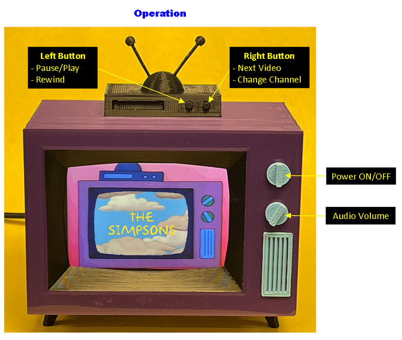
Operation of the Simpsons TV is pretty straightforward:
- Press the power button to turn the TV ON/OFF. When powering ON, it will take about 15-20 seconds for the Pi to boot. Once booted, the Simpsons TV will automatically start playing videos from the first channel.
- Turn the audio volume knob to increase / decrease volume
- Left Button Operation:
- Quickly tap the left button to pause or play the current video
- Press and hold the left button for > 1 second to rewind 10 seconds (continue holding to keep rewinding)
- Right Button Operation:
- Quickly tap the right button to select the next video in the current channel
- Press and hold the right button for > 2 seconds to select the next channel
- Press and hold BOTH the left and right buttons at the same time for > 5 seconds to stop video playing and exit the Python script to a command prompt (NOTE: None of the buttons will work at this point, including the power button – you will need to connect a keyboard or SSH into the TV and execute a “sudo shutdown now” command to properly shutdown the Pi or restart the player.py Python script to re-enable button functionality).
Step 21: Useful Raspberry Pi Linux Commands
This section provides a list of Linux commands I found useful during development and use of this project. I hope you find them useful as well.
How to exit a Python terminal and Shutdown OMXPlayer instance:
When you connect to “The Simpsons TV” via SSH, it will execute another instance of the python player.py script. This will start up another independent version of the omxplayer, which will start playing another video. This can result in multiple videos trying to play at the same time (glitchy video and overlapped audio). To kill this new omxplayer instance, do the following:
- When you establish a new SSH session, your terminal will be inside a python terminal window. To exit this terminal, type “Ctrl-A-\“.
- At the resulting raspberry pi prompt, type, “pgrep -a omxplayer“. This will list all current instances of the omxplayer and their process IDs.
- Note the process id of the LAST instance of omxplayer – type “sudo kill <process id>“. This will kill the new omxplayer instance that was started by the SSH connection.
Below is an example of this sequence of commands:
pi@raspberrypi:~ $ pgrep -a omxplayer
756 /bin/bash /usr/bin/omxplayer /home/pi/simpsonstv/videos/The Simpsons/Season 1 - Episode 01.mp4
768 /usr/bin/omxplayer.bin /home/pi/simpsonstv/videos/The Simpsons/Season 1 - Episode 01.mp4
pi@raspberrypi:~ $ sudo kill 768
pi@raspberrypi:~ $ Terminated
How to Change WiFI SSID and/or Password:
sudo nano /etc/wpa_supplicant.conf
After making edits, save the file by typing Ctrl-o, hit <ENTER>, then exit the editor by typing Ctrl-x.
How to copy movies from USB drive to SD Card “Channel”:
sudo cp /media/usb/<directory>/* ~/simpsonstv/videos/<channel>
where <directory> is the directory name on the USB drive to copy from, * is a wildcard to copy all files in the <directory> or explicit filename to copy, and <channel> is the directory on the Pi's SD card to copy to. Note: You must include quotes if the file or directory name has spaces in it (i.e. “The Simpsons” for example).
How to Eject a USB Drive from the Pi:
sudo eject /dev/sda1
How to Automatically Install Package Dependencies for a Failed Package Install:
sudo apt --fix-broken install
This works after the package install fails due to missing package dependencies.
How to Edit the player.py Python script:
sudo nano ~/simpsonstv/player.py
Modify the script and make it your own, giving it whatever functionality you like! After making edits, save the file by typing Ctrl-o, hit <ENTER>, then exit the editor by typing Ctrl-x.
How to Make New “Channel” Directories
sudo mkdir ~/simpsonstv/videos/<channel>
where <channel> is the directory name you want to create for a “Channel”. Note: You must include quotes if the directory name has spaces in it (i.e. “Reality TV” for example).
Step 22: Closing