
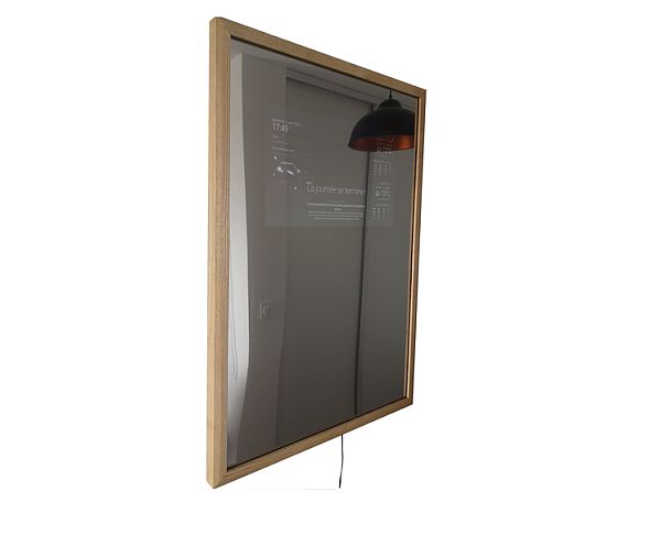
The goal of this project is to create a Magic Mirror which gives the impression of being a simple mirror and not a connected mirror. The design is based on reusing recycled materials, especially for the screen. Two video tutorials are available for this fabrication.
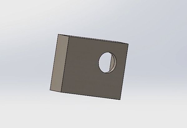
Step 1: MANUFACTURING PLANS
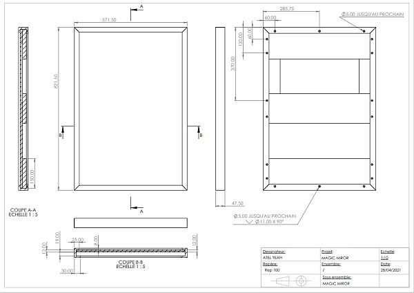
The manufacturing plans of the MAGIC MIRROR.
Step 2: LIST OF COMPONENTS
– Wood Tassot link /Wooden Tassot link:
https://www.bricodepot.fr/catalogue/botte-de-8-tas…
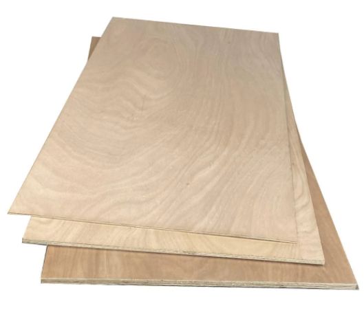
– Plywood panel link / wood panel link: https://www.bricodepot.fr/catalogue/predecoupe-co…
– Plexiglass link / Plexiglass link:: https://www.bricodepot.fr/catalogue/verre-synthet…
– Noise Filter:: https://fr.aliexpress.com/item/1005001568096503.h…
-Raspberry Pi 3B+ / Raspberry Pi 3B+: https://fr.rs-online.com/web/p/raspberry-pi/81112…
– 12V to 5V transformer / 12V to 5V transformer: https://fr.aliexpress.com/item/1005002411614827.h…
– Loudspeakers / Speakers:: https://fr.aliexpress.com/item/1005001297672286.h…
– Micro USB / USB Microphone: https://uk.aliexpress.com/item/1005002316982769.h…
– Screen control board / creen control board: https://fr.aliexpress.com/item/4000427568393.html…
– 3W amplifier / 3W amplifier: https://fr.aliexpress.com/item/33010669409.html?g…
– Mirror film / Mirror film: https://fr.aliexpress.com/item/4000123200462.html…
-12V power supply / 12V power supply: https://fr.aliexpress.com/item/32859196804.html?s…
-Humidity and temperature sensor: https://fr.aliexpress.com/item/1005002541542850.h…
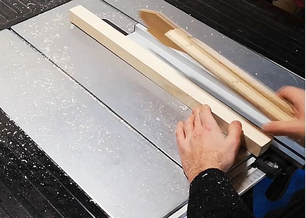
Step 3: CHOICE OF WOODS FOR THE FRAME AND DEBIT
If possible, buy wooden tassots which will avoid any additional processing. Likewise for the sleepers, it is easy to select wood of the right thickness. Then it is necessary to edge the crosspieces using the circular saw on the table. For the 6mm plywood bottom, you must use a circular saw, otherwise simply have it cut to size in store.
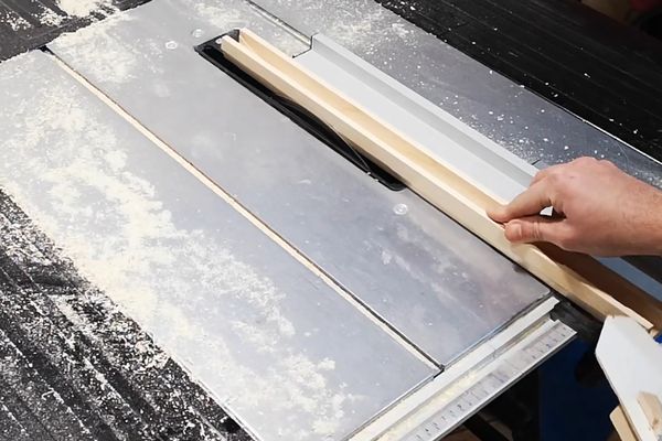
Step 4: GROOVE PROFILING
In order to have the space to place the plexiglass and the plywood, a wide and deep groove must be made. You can use a router or table saw for this. You have to make several passes.
Step 5: MOLDING PROFILING
In order to have a more aesthetic shape, a profiling of a chamfer is made on the front outer edge using the table saw. Simply set the desired angle and the measurement of the parallel guide.
Step 6: LENGTH CUT
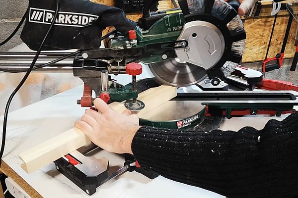
It is only necessary to cut to length with the radial circular saw. These length cuts are made at a 45° angle.
Step 7: RABBET PROFILING RAILS
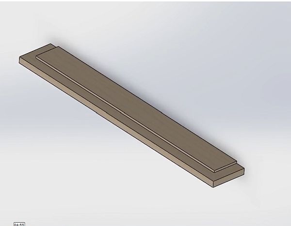
These rabbets are made using the table saw but they can also be made using a router. There is a rebate along the length of the upper and lower crosspieces, and a rebate at the end on both sides of each of the crosspieces.
Step 8: FRAME AND STRUT DRILLING
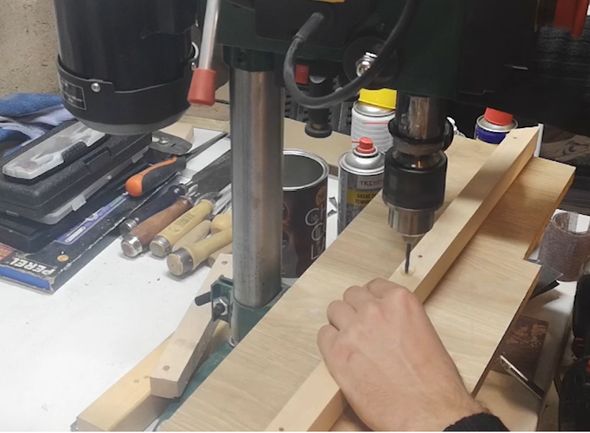
The crosspieces are assembled with the frame using glue and screws. To start, it is therefore necessary to drill with a 4mm bit then countersink for the passage of the screw heads. Also make a notch in the middle of the upper crosspiece in order to have a blockage when the frame is on the wall. It is also necessary to make a hole for the passage of the PIR sensor. For my part it is below, this allows me not to see any drilling on the front to keep the mirror effect simple, and above all I can use the mirror without the MAGIC MIRROR activating against my will.
Step 9: SANDING AND GLUING
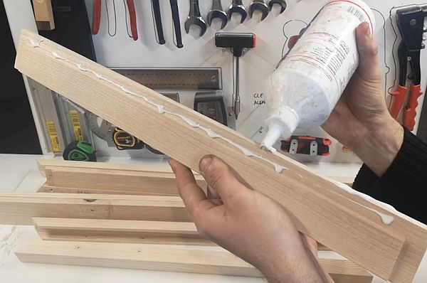
The parts must be sanded before gluing in order to simplify the finish. Start at grit P100 then P120 and then P150. Thereafter it is necessary to proceed to the bonding of the upper and lower crosspieces on the upper and lower part of the frame. Then, once the glue has dried, you can glue the miter cuts of the lower part of the frame using a ratchet strap, tightening the whole assembly, and glue the crosspieces in the middle by applying glue at the end of the sleepers. you have to screw the screws that connect the frame to the crosspiece. Attention, do not glue the cuts of the upper crosspiece in order to be able to dismantle the frame by this part.
Step 10: CUTTING AGAINST PLATE
There is the possibility of buying a plate already with dimensions in store by paying for the cut, otherwise you can cut using a circular saw, on table and portable, or with a jigsaw. It is necessary to adapt the plywood so that it fits into the frame, leaving 2 mm of play.
Step 11: NOTCH AGAINST PLATE FOR SCREEN
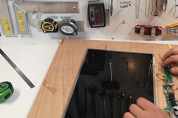
You have to make a cut in the plywood to make room for the screen. This notch is made using a portable circular saw to have straight edges, then finish cutting them using a hand saw or a jigsaw. With the offcuts, make the screen retaining stops.
Step 12: RASPBERRY PI NOTCHING AND PIR SENSOR
In order to keep a thin mirror in thickness, it is necessary to notch the plywood in order to leave room for the Raspberry pi. So it does not go beyond the frame. This notch is made using a wood chisel.
The notch at the bottom of the plywood will allow the installation of the PIR sensor. I did it after finishing the plywood in the tutorial, but it's best to do it now.
Step 13: TEST ASSEMBLY
This step is not compulsory, but it is recommended in order to check that the plexiglass and the plywood pass well through the frame before carrying out the finishing.
Step 14: FRAME SANDING AND FINISHING
The glue must be cleaned if necessary (be careful otherwise there will be finish defects), sand the whole thing, finishing with the P150 grain, then apply black paint on the plywood, then varnish it. Following this coat of varnish, perform a scuffing pass using a P400 grit, then apply a second coat of varnish. The operation must be repeated depending on the desired surface condition. For the frame it is necessary to apply varnish. Then you have to perform a scuffing pass using a P400 grit, then apply a second coat of varnish. The operation must be repeated depending on the desired surface condition. You must always finish with a coat of varnish which is therefore the finishing coat.
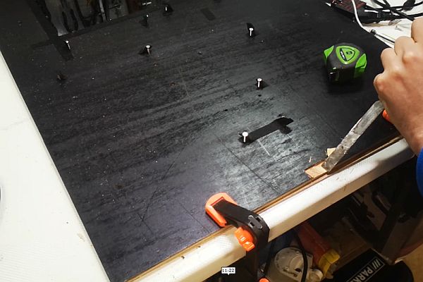
Step 15: BACK PLATE FINISH
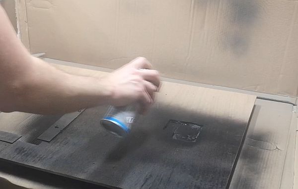
So that the plywood cannot be seen through the plain mirror, the plywood must be painted with black paint.
Step 16: FLOW OF PLEXIGLASS OR GLASS
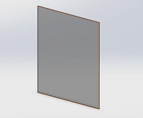
For the plexiglass there is the possibility of buying a plate already with dimensions in store by paying for the cut, otherwise, you can cut using a circular saw, on a table and portable, or with a jigsaw for plexiglass. For glass, you must use a glass cutting tool and dearomatized petroleum. You have to cut the glass using the tool and a ruler, apply petroleum which helps with the cut, then tap on the back of the cut using the tool, which extends the notch, then give a jerk to make the cut. Please note the glass is not polished and is therefore very sharp. The glass or plexiglass must be adapted to the dimensions of the plywood.
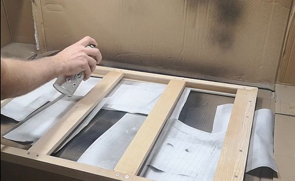
Step 17: UNDYED FILM VENEER
In order to have the mirror effect, colorless film must be applied to the plexiglass panel. To do this, you must use soapy water and a squeegee. You need to cut a sheet of colorless film larger than the plexiglass plate, then spray soapy water on the plexiglass panel, then remove the protective film on the colorless film and apply it to the panel. Then you have to chase the soapy water between the two using the squeegee. Finally, you have to cut off the excess film without shades.
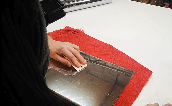
Step 18: REMOVING OF A SCREEN
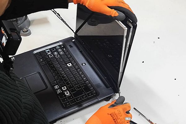
The screen used is a recovery screen. It was disassembled into a broken laptop. A reference is on the back of the screen, and it is from this that we can find a power supply module that will power the screen and connect it via HDMI with the Raspberry Pi.
Step 19: MIRROR ELECTRONICS
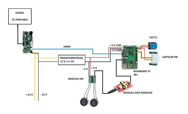
Here is the electrical diagram for using the mirror. So there are these components:
-raspberry Pi 3B+
– 12V power supply board suitable for the screen recovered from an out of order laptop
– a screen slab recovered from an out of order laptop
-12V to 5V 10 A transformer
– 12V power supply
– 3W amplifier
– 4W speaker
– anti-parasite module
-a microphone connected via USB
– a cut USB cable to power the raspberry Pi
– A DHT 11 humidity and temperature probe
-A Pir sensor to wake up the magic mirror
– connection cables for the GPIO pins and for the Pir sensor as well as the DHT 11 sensor
-wires to power the various elements: the 12V power supply module of the screen, the raspberry pi in 5V, the 3W amplifier module in 5V
Step 20: ELECTRONIC BOARD MOUNTING DRILLING
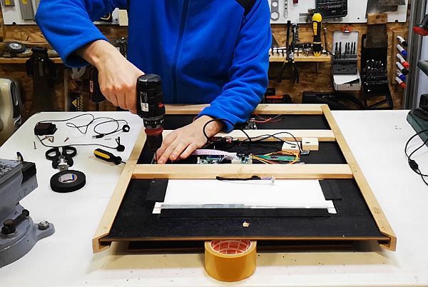
The electronic cards are put in place on the plywood panel. For this it is necessary to make holes with a diameter of 3mm in order to maintain the cards with m3 countersunk heads and nuts. Only the Raspberry pi must be set up differently, the card has 2.5 mm diameter holes. In order to keep the same 3mm screws, you have to make a small plastic plate to hold the card, and it is this one that is drilled with the 3mm diameter holes. It is then necessary to countersink the holes in order to leave room for the screw heads.
Step 21: AUDIO SYSTEM
In order to have a vocally connected mirror, you must add a USB microphone, as well as speakers. The loudspeakers are small and require a sound box. They must also be connected to a 3W amplifier. The advantage of this system is that it is thin for good power. The amplifier is supplied with 5V and is therefore connected to the 12V to 5V transformer.
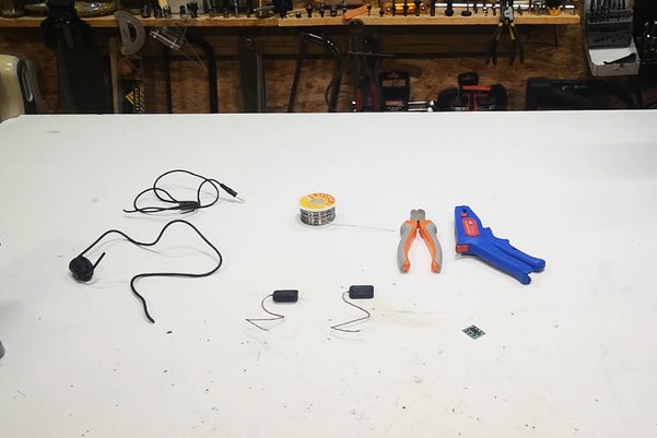
Step 22: SPEAKER BOX
In order to make maximum use of the power of the loudspeakers, it is necessary to make boxes of 50 mm X 40 mm X 12 mm. These are made using 3 mm plywood, cut at 45°, drilled using a 15 mm drill bit (in order to place the loudspeakers), and glued flat. vinyl glue and tape. The tape is to be removed after drying. These boxes have no bottom, this is obtained with the plywood panel of the structure. To ensure the connection between these boxes and the panel, they will be glued with a glue gun when the assembly is assembled.
Step 23: SCREEN MOUNTING
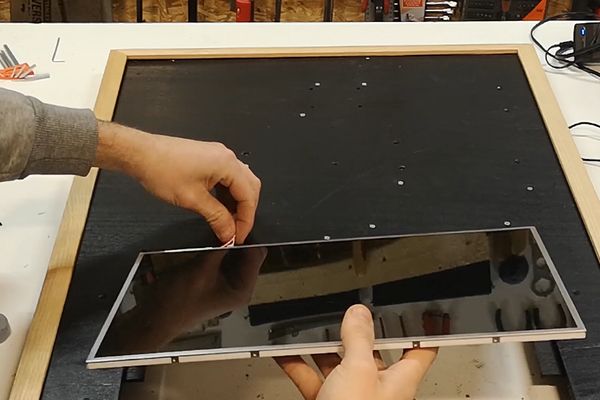
The screen must be placed on the plywood, taking care not to drop it, then put in place all the fabric tape around the frame of the screen in order to avoid the highlights which would be seen below the film without complexion.
Read more: THINNEST MAGIC MIRROR