
Kids just aren't huge fans of brushing their teeth. Not only are they not huge fans, they also are pretty bad at it. Teaching a young kid to brush their teeth is really hard. I created a little contraption that not only times them to make sure they brush for an entire two minutes, but also tells them what part of their mouth they should be brushing! Now kids can't claim they didn't know what to do, since the Toothbrush Instructor told them!
Step 1: Supplies
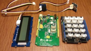
Picture of Supplies
We'll make use of quite a few different grove sensors here for fast and easy prototyping. If you can, pick up the Arduino Grove Starter kit. It comes with a Grove base shield that is compatible with the LinkIT ONE, and tons of different sensors (and also the exact ones you need for this project!).
LinkIT ONE Board
Grove RGB LCD
Grove Button
Grove Arduino Base Shield
Grove Buzzer
Step 2: Hooking up all your Grove Sensors
Picture of Hooking up all your Grove Sensors
WP_20151111_010.jpg
WP_20151111_009.jpg
Firs step might be pretty obvious: Hook up all those Grove Sensors! Because we're using Grove, it makes it easier than ever to connect and interface with sensors. Simply plug in your Arduino Base shield to the LinkIT ONE (the pins should match up perfectly) and then plug in the different sensors.
Plug the RGB LCD into an I2C port.
Plug the Buzzer into D2
Plug in the Button to D3
Step 3: Controlling the RGB LCD
Picture of Controlling the RGB LCD
First, let's take a look at controlling our RGB LCD. In order to interface with the Grove RGB LCD, you'll need to download their external library here and install it to your Arduino IDE. I've attached the code file for you to review, but let's walk through it a bit to make sure we understand it.
#include “rgb_lcd.h”
First, make sure to include the RGB LCD library so we can easily control our lcd.
rgb_lcd lcd;
const int colorR = 0;
const int colorG = 0;
const int colorB = 230;
lcd.setRGB(colorR, colorG, colorB);
Now, create an RGB LCD object for us to control. Set some default colors (we'll just stick with blue, you're free to mess with this though!)
lcd.print(“Hello, World!”);
Now, print something to the screen!
Step 4: Controlling the Button and Buzzer
Picture of Controlling the Button and Buzzer
Next, let's go through how we will control the button and buzzer. Let's set it up so that the button will trigger the buzzer to ‘buzz'.
pinMode(6, OUTPUT);
pinMode(buttonPin, INPUT);
Define the pins that the button and buzzer are connected too.
if (digitalRead(buttonPin) == HIGH) {
//Button is Pressed!
}
For the button, we'll detect a ‘HIGH' signal. That means that the button is pressed down. ‘LOW' means it is un-pressed.
//Buzz the Buzzer!
digitalWrite(6, HIGH);
delay(analogRead(0));
digitalWrite(6, LOW);
delay(analogRead(0));
For the buzzer, we'll do something similar. We'll emit a LOW signal when we want it to be off, and a ‘HIGH' signal when we want it to buzz!
For More Details: Toothbrushing Instructor