
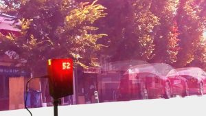
Want to track the license plates of speeding cars with a traffic camera that is 40 times cheaper than that of a commercial one? This Instructable shows how you can use the Raspberry Pi, Camera Module v2, 8×8 LED Matrix,and OPS243 Radar Sensor to obtain the license plates of vehicles speeding up to 60 mph!
What you'll gain from this project includes the following:
- Intermediate Python programming techniques (e.g., os and multiprocessing libraries, and modular programming)
- Basics of Linux Shell Commands (e.g., nano)
- Basics of 3D Printing
- Intermediate Electronics/Hardware Setup (e.g., LED Matrix, OPS243)
Supplies
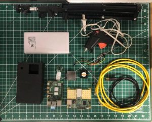
Single-Board Computer and its Peripherals
- Raspberry Pi 3/3 Model B+/4 Model B and Power Supply/Adapter
- OPS243 Radar Doppler Sensor (-A or -C)
- Raspberry Pi Camera Module (v1 or v2)
- Battery Pack of at least 20,000 mAh and 2 A Output
- (Recommended) 8×8 LED Matrix
- (Recommended) Raspberry Pi Cooling Fan
- (Recommended) PC Laptop for rapid testing
- (Recommended) Display Monitor, Keyboard, and Mouse, or “Headless Mode” via SSH or Remote Desktop
Wiring
- USB Female to USB-C
- USB 2.0 A-Male to Micro B
- (5) Five Male-to-Male Dupont Wires
- (Recommended) Ethernet Cable
Camera Enclosure
- 3D Printer of Bed Size 235 x 235 mm, and 200g of PLA Filament or Online Purchased Raspberry Pi Enclosure
- Camera Tripod
- (1) One 1/4-20 Hex Nut
Miscellaneous
- Flat head screwdriver
- Soldering Iron or Hot Glue Gun
- (Recommended) Duct tape
The supplies in typefaced in bold are the ones used for this Instructable.
Step 1: Download Python Project
Download Python Project “traffic_camera_project” linked here. Alternatively, you may download the code directly by entering the command line:
$ git clone https://github.com/pedrigalchristian/traffic-camera-raspberry-pi.git
traffic_camera_project
|—- README.txt
|—- traffic_camera
|—- |—- __init__.py
|—- |—- camera_config.py
|—- |—- file_org.py
|—- |—- serial_interface.py
|—- |—- led_dot_matrix.py
|—- |—- license_plate_recognition_API.py
|—- |—- _testUSB.py
|—- |—- _test_picamera.py
|—- main.py
main.py. This is the main program that is run for the traffic speed camera. It imports all the five modules in the package traffic_camera: camera_config.py, file_org.py, serial_interface.py, led_dot_matrix.py, and license_plate_recognition_API.py.
README.txt. This is a text file that reads the details of the project.
camera_config.py. This module creates a PiCamera.picamera object, sets its initial configurations, and runs a background process for continuous camera capture.
file_org.py. This module involves all functions related to creating/removing folders and moving files around to different folders.
serial_interface.py. This module involves all functions related to reading and writing data from the USB interface established between the OPS243 Radar Doppler Sensor and the Raspberry Pi. Requires a third-party library installation (shown in Step 2).
led_dot_matrix.py. This module involves all functions and objects related to the 8×8 LED Dot Matrix. Requires a third-party library installation (shown in Step 2).
license_plate_recognition_API.py. This module runs a background process for sending speeding vehicle photos to the License Plate Recognizer API.
_testUSB.py and _test_picamera.py. These modules assist in unit testing the traffic camera, such as ensuring that data is being read from the OPS243 and that the Raspberry Camera Module is working properly and taking photos towards the desired direction.
Step 2: Download Third-Party Python Libraries
On Raspberry Pi terminal, run the following Linux Shell Commands to install the third-party Python libraries used for this project:
Pyserial: Allows to read and write data to serial interfaced peripherals
$ python -m pip install pyserial
MAX7219: Allows to program 8×8 LED Matrix with Python
$ sudo apt-get install python-dev python-pip
$ sudo pip install max7219
Step 3: Configure Settings of Raspberry Pi
Update Raspberry Pi. Run the following command on the Raspberry Pi terminal:
$ sudo apt update
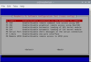
Enable Camera and SSH on Raspberry Pi Configuration. Run the following command on the Raspberry Pi terminal:
$ sudo raspi-config
Under the Interfaces tab, Enable Camera and SSH. You may need to restart the Raspberry Pi for these changes to take effect.
Edit /etc/profile script so that project runs upon startup. Run the following command on the Raspberry Pi terminal:
$ sudo nano /etc/profile
Scroll to the bottom and add the following line:
$ sudo python /home/pi/traffic_camera_project/main.py
Exit the script by pressing Ctrl+X, Y, and Enter. Now, the board will run the python script as soon as it is finishing powering up. More information on configuring Python scripts upon startup can be seen here.
Step 4: Create Account on License Plate Recognizer
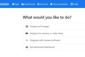
The traffic camera uses the free version of License Plate Recognition API in order to recognize the license plates of vehicles from still images. For the free version, there are up to 2500 images that can be called to the API per month.
Create free account. On the home page of License Plate Recognition, create a free account.
Keep record of Token. From the top bar, access the Account page to view Token that is unique to your account. Keep record of this Token, as this will be modified on the main.py script in the following step (Step 5).
Step 5: Modify User Arguments on Main.py
Access main.py from traffic_camera_project. From Step 1, the entire Python code should already be downloaded onto the Raspberry Pi. Open the Python script main.py.
Modify User Arguments. On lines 37 to 40, there are four user arguments that can be modified to the user's application of the project, such as the speed at which the traffic camera will begin taking pictures and where these photos will be stored. Change the values of these four variables to your application.
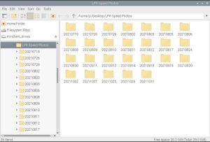
speed_limit = 10 # in mph
main_folder = "LPR Speed Photos" # Name of your main directory
parent_directory = '/home/pi/Desktop/' # Location of your main directory
token = YOUR_UNIQUE_TOKEN_FROM_STEP_4
The speed_limit is an integer variable that reflects the speed limit of the street the traffic camera is monitoring.
The main_folder is the name of the main directory for which photos will be stored on the Raspberry Pi.
The parent_directory is a string variable of the path of main_folder.
The token is a string variable of the token value obtained from Step 4.
**Note: In a future revision, the argparse Python library will be implemented to the main.py script so that the user can input these arguments from the command line instead of having to open an editor to modify these four variables.**
Step 6: Configure OPS243 Doppler Radar Sensor
Connect OPS243 Doppler Radar Sensor to Raspberry Pi. With the USB 2.0 A-Male to Micro B cable, plug in the sensor to any port on the Raspberry Pi. The OPS243 can communicate with other interfaces, such as UART and Wifi, but in this particular project, data will be communicated via serial interface.
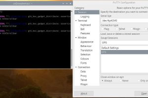
Access Report Data from Radar Sensor from PuTTY. PuTTY is a free SSH client that enables the report data from the OPS243 to be conveniently read. If not already on the Pi, please download the program on their official website.On the Raspberry Pi terminal, access PuTTY with the following command:
$ putty
Alternatively, PuTTY can be run on the terminal of your PC Laptop; the radar sensor may simply be connected to your laptop first before connecting it again to the Raspberry Pi.
Modify Persistent Settings for OPS243. Conveniently, the OPS243 Doppler Radar Sensor uses simple keyboard commands to read or write its current settings. All keyboard commands can be viewed from the official documentation from OmniPreSense here.
The following keyboard commands are used:
For Both OPS243-C and -A
- Oz (Disable Ignoring Watchdog Timer for USB Tx
- S1 (Set Doppler Sampling Rate to 10k Hz)
- US (mph Speed Unit Setting)
- BV (Do not output blanks)
- R>10 (Reported Speed Minimum Filter Setting at 10 mph)
- OJ (Turn on JSON format)
- M>150 (Minimum Speed Magnitude at least 150)
For OPS243-C Only:
- r>20 (Reported Minimum Distance at 20 feet away)
- r<60 (Reported Maximum Distance at 60 feet away)
- OY (Combo Output)
After these changes are made, you can view the current settings using the ?? command. Save the current settings as persistent using the A! command. This means that these modified settings will remain after unplugging the sensor.
Step 7: Configure Raspberry Pi Camera Module
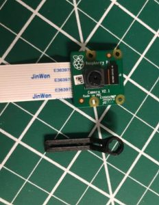
Fix Blurry Focus of Raspberry Pi Camera. Although the official Raspberry Pi website claims that their Camera Module has an auto focus, those who worked with their camera knows of how inherently blurry the $20-30 hardware can be. This can be easily fixed manually adjusting the focal lens of the camera module using a flat head screwdriver. Even better than a screw driver is an Adafruit Lens Adjustment Tool for under $1.00, or one that you can 3D printed this same tool from stl files online.
From Jeff Geerling's blog post on manually adjusting the focal lens, the following procedure was used for this particular project:
- With the flat head screwdriver, rotate the lens CW until there is a mechanical stop. This will be the reference angle for next step.
- From the reference angle, rotate the lens CCW by 0.875 of 1 full rotation, which is 7/8th of a full rotation. In order to track the turn, pay close attention to one of the notches while turning the focal lens.
With this manual focal lens adjustment, the Camera Module should be able to have refined images of objects approximately 60 feet away or closer.
Step 8: Finalize Hardware Setup
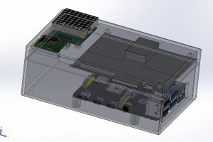
Option #1: 3D Printing
- Print the following STL files on 3D Printer with PLA Filament. See the attached STL files for the Top Enclosure and Bottom Enclosure. The print time is approximately 8 hours each, for a total of 16 hours. Intermediately long print jobs such as these necessitate for proper job preparation and calibration. Please review online resources for further information.
- Insert Hex Nut into 3D Printed Object. After successful print jobs, insert the 1/4″ 20 Hex Nut into the Bottom Enclosure print using a soldering iron to melt the nut into the object, or more conveniently, using a hot glue gun. This Instructable uses a hot glue gun, the more pragmatic but less rigid option. See the image above for results.
Alternative Option #2: Purchase Raspberry Pi Case Online. While having a 3D printed part customized for this project is ideal, not many individuals have access to a 3D printer. Therefore, here is an alternative Raspberry Pi Case that can be mounted to a Tripod Camera. For attaching the other hardware, please use fastening techniques such as duct tape or hot glue for effective rigidity.
Insert Hardware Into Camera Enclosure.
- Connect Camera Module to Raspberry Pi. The strip camera module is inserted into the board of the Raspberry Pi like so. The camera itself is snapped into the top enclosure of the 3D printed object. {Insert Image}
- Wire 8×8 LED Matrix to Raspberry Pi. There are 5 pins that need to connected to the GPIO pins of the Raspberry Pi board: VCC, GND, DIN, CLK, and CS using the male-to-male Dupont wires. The image above taken from the MAX7219 Python library shows the Pin Assignments.
- Connect OPS243 Doppler Radar Sensor to Raspberry Pi (if not already). The radar sensor is connected to the board via USB cable. The radar sensor itself is snapped into the top enclosure of the 3D printed object. {Insert Image}.
- Connect Battery Pack to Power Supply of Raspberry Pi. Using the USB Female to USB-C cable, connect the battery pack to the power supply port of the Raspberry Pi. Though the Raspberry Pi 4 requires 3.5 A, the 2 A output from the battery pack was proven sufficient. It was found that the maximum power consumption of the traffic camera project is approximately 1.3 A, so be aware of the battery size for the needs of your project. For example, using 20,000 mAh Li-Ion Battery Pack, it is expected that the traffic camera will last for approximately 13 hours before re-charge.
- (Optional) Wire Cooling Fan to Raspberry Pi. The cooling fan is wired to the 5V and GND GPIO pins of the Raspberry Pi board. Please see the attached image to view the pinout diagram of the Raspberry Pi. (Some cooling fans online come with fastening screws for direct placement on board, but any placement for effective cooling is fine for this project.)
Place Traffic Camera on Tripod. After all hardware is properly secured into enclosure of choice, attached the traffic camera onto the camera tripod via hex nut. (From previous experience, it is better to screw the tripod onto the camera rather than the camera onto the tripod.)
** Note: If the hardware is not able to be snapped into the 3D printed object as expected, please use other fastening techniques like duct tape or hot glue as temporary solutions.**
Step 9: Test Python Project Indoors Before Outside
Before taking the traffic camera to the road, it is safe to test for any immediate issues that may arise. Please review that all previous steps are performed correctly. Otherwise, one of the following issues will arise.
Hardware Issues
- No connection established between OPS243 and Raspberry Pi
- Improper wiring of LED Matrix onto Raspberry Pi
- Improper wiring of Cooling Fan onto Raspberry Pi
- Improper attachment of Pi Camera onto Raspberry Pi
Software Issues
- Previous steps involving configuring Raspberry Pi
- Previous step involving modifying main.py script
- No Wi-Fi connection for LPR
Step 10: Optimize Camera Mount Angle
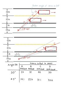
Determine Mount Height. According to traffic laws, the maximum height for the placement of license plates is 5 feet. However, most license plates are no more than 2 feet from the ground. Low heights of 1 to 2 feet of the tripod are effective mounting heights.
Determine Mount Angle. Determining the mounting angle is a bit trickier. Referring to the diagram above, one can see that these parameters depends on the (1) how far the traffic camera is placed on the sidewalk, (2) how far the camera wants to begin detecting the speeding cars, (3) how many lanes the traffic camera wants to detect, and (4) the width of the individual traffic lanes. Assuming the standard width of each traffic lane as 12 feet, the traffic camera is placed 5 feet from the sidewalk and placed at 45 degree angle in order to effectively detect two traffic lanes at distances between about 22 and 40 feet away.
It is important to note that the traffic camera angle for a single-lane configuration should place a 30 degree angle. This should detect vehicles between about 32 and 50 feet away.
This should be determined by how focused the camera lens is to detect the license plates of vehicles at long distances. Based on the focal lens adjustment in the previous step, the camera was able to effectively focus on cars up to 60 feet away.
Source: Traffic Radar Speed Sensor and Camera That Recognizes License Plates