
Servos are similar to motors, but can typically only move from 0 to 60/120/180 degrees, rather than rotate continuously. Unlike a motor, you send a servo a signal that makes it go to a specific position (eg 30 degrees), making them ideal for applications such as moving parts of robots, or controlling surfaces on an aircraft. That’s a little complicated to cover in this tutorial – a simpler use case is using a servo to turn an analogue potentiometer. Here we are going to create some simple software that will allow a Raspberry Pi to control the volume knob on a simple speaker amplifier, which could be used as part of a remote control project. This step- by-step tutorial assumes that you have already soldered the pin headers onto the Adafruit board.
What you’ll need
Latest Raspbian image
Adafruit PCA9685 servo controller
5V power supply
Female-to-female jumper cables
A servo suited to your needs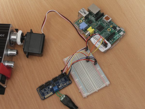
Step-by-step
Step 01 Install software and configure I2C
We will start off with the usual ‘apt-get’ lines. Simply enter the following commands in order to download and install the required software:
$ sudo apt-get update
$ sudo apt-get install python-smbus i2c-tools git
$ git clone https://github.com/adafruit/Adafruit-Raspberry-Pi-Python-Code.git
By default, the I2C modules are blacklisted. To change this, run:
$ sudo nano /etc/modprobe.d/raspi-blacklist.conf
…and comment out the following lines by putting a # in front of each of them:
blacklist spi-bcm2708
blacklist i2c-bcm2708
Save changes with Ctrl+O followed by Enter, then exit with Ctrl+X. Then, you also need to add the following two lines to /etc/modules:
i2c-dev
i2c-bcm2708
Finally, run sudo poweroff to shut down the Raspberry Pi.
Step 02 Wire the servo controller
Wire up the servo controller, as shown in the circuit diagram. It’s essential that all power is disconnected during the wiring process. You also need to make sure that your Raspberry Pi is oriented the correct way. The OE pin on the Adafruit board stands for Output Enable and is active low, which means the output is enabled when the signal is 0V. This is why we have connected it to ground. The VCC pin on the Adafruit board should be connected to 3.3V from the Raspberry Pi and the servo power in the middle of the board should be 5V. The Raspberry Pi’s power needs to be stable – and servos often cause a voltage drop, which is why a second power supply is necessary.
Step 03 Test the connection to the servo controller
We will use a program called i2cdetect to detect the servo controller. If you are using an older Raspberry Pi then the I2C bus is 0, otherwise the I2C bus is 1. Type sudo i2cdetect -y 1, where 1 is the I2C bus number. You should see an output similar to the one in the image. Try the other I2C bus and, if not, then it’s likely you’ve wired something wrong.
Step 04 Servo Hello World
Change directory into where you git-cloned the Adafruit Raspberry Pi code (it was probably /home/pi). Then run the following commands:
$ cd Adafruit-Raspberry-Pi-Python-Code
$ cd Adafruit_PWM_Servo_Driver
$ sudo python2 Servo_Example.py
If your servo is connected to channel 0 of the Adafruit board, it should start moving between its min and max positions.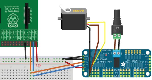
Step 05 How a servo works
If you open up the Servo_Example.py code in nano, you’ll see that there isn’t much to it. This is because the Adafruit board does all of the hard work and the Raspberry Pi just tells it what to do. The Adafruit board is required because a servo requires very accurate pulse-width modulation signals to set its position. This is very hard to do on a Pi because there are so many other things going on.
If you look at the two oscilloscope traces, you can see what the Adafruit board sends to the servo. The difference in the duty cycle (the percentage of time that a signal is high) between the minimum position and maximum position is roughly 10 per cent.
Step 06 Run the code
Place the code in the same directory as the Adafruit example code and run it with sudo python2 Servo_VolumeControl.py. The servo should rotate to the right when you press the up arrow and rotate to the left when you press the down arrow.
For more detail: Use your Raspberry Pi to move parts of a robot or control anything that can rotate