
Contents
hide
I have a Raspberry Pi – this post is about beginning to explore it's control capabilities using the General Purpose Input Output (GPIO) port and is aimed at total beginners assuming that you have already got your Raspberry Pi up and running as described in my earlier post Fire up your Raspberry Pi.
Hardware
The GPIO port is the two rows of pins coming out of the black plastic header shown running horizontally along the top of the board shown above. Each pin has a number with pin one identified as P1. Each pin does a specific job such as provide a voltage, ground, data input or output. There are different types of input/output that may be used depending on your requirements.
To start with I wanted to make a simple circuit just to get my feet wet. I bought a kit from the internet (for £7.50 April 2013) that included a ribbon breakout cable, a breadboard and some LEDs, push switches and resistors. Enough to get me started. Later on I read another blog that suggested a more convenient cable to connect the board header to the breadboard.
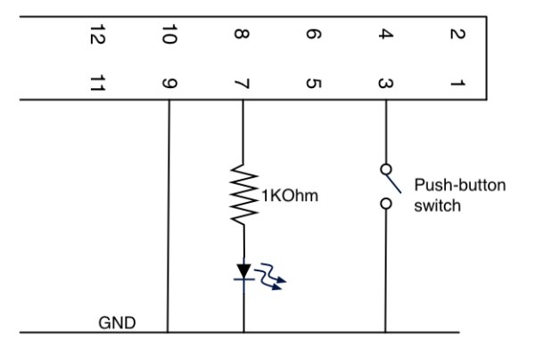
But what do I do with it? A google search should throw up many options, I started with a very simple one following a tutorial from Limina.Log embellished with some extra info from LWK's Arduino Projects. I ended up with two circuits on my breadboard. The one on the left simply push button to light LED using power from the Raspberry Pi, the second passed a button pressed event to the Raspberry Pi that would then switch the LED off and on.
The Raspberry Pi GPIO Pin Outs are described well by Cyntech/Pimoroni's cheat sheet. Each pin can be programmed individually, they also work together for certain standards such as SPI, I2C and UART as described by the coloured highlights. For example Pin 8 is TXD for UART, it is also individually programmable as GPIO14. The way the break-out cable is wired produces a mirror image of that map on the breadboard as shown in the 2nd circuit diagram above. The pins I am using are P3: GPIO2, P7: GPIO4, P9: GND.
Software
At the Raspberry Pi command line (or ssh from laptop or mobile) I installed rpi.gpio using the following command – this only needs to be done once.
sudo apt-get install rpi.gpio
Now I used python to control start controlling the hardware on the breadboard. Python should already be installed with your Raspberry Pi OS (see my other post on installing Raspbian Wheezy)
python
>>> import RPi.GPIO as GPIO
>>> GPIO.setmode(GPIO.BOARD)
>>> GPIO.setup(7, GPIO.OUT) That's the setup bit done, now to manually switch the LED on and off on by controlling P7.
>>> GPIO.output(7, True)
>>> GPIO.output(7, False)
Next to try out the input on P3 that is connected to the push switch.
>>> GPIO.setup(3, GPIO.IN)
>>> GPIO.input(3)
Re-run that last command with push switch off returns 1; with push switch on returns 0. Finally I wrote a small while loop to listen to the push button and turn the LED off accordingly. To input the while loop here you need to type the tabs as shown by <tab> and <return> a blank line at the end to kick it off.
>>> while 1:
… <tab>if GPIO.input(3):
… <tab><tab> GPIO.output(7, False)
… <tab>else:
… <tab><tab> GPIO.output(7, True)
…
This is a video of what this all does – it's not much but it lays the foundation for so much.
sudo apt-get install rpi.gpio
Now I used python to control start controlling the hardware on the breadboard. Python should already be installed with your Raspberry Pi OS (see my other post on installing Raspbian Wheezy)
python
>>> import RPi.GPIO as GPIO
>>> GPIO.setmode(GPIO.BOARD)
>>> GPIO.setup(7, GPIO.OUT)
 That's the setup bit done, now to manually switch the LED on and off on by controlling P7.
>>> GPIO.output(7, True)
>>> GPIO.output(7, False)
Next to try out the input on P3 that is connected to the push switch.
>>> GPIO.setup(3, GPIO.IN)
>>> GPIO.input(3)
Re-run that last command with push switch off returns 1; with push switch on returns 0. Finally I wrote a small while loop to listen to the push button and turn the LED off accordingly. To input the while loop here you need to type the tabs as shown by <tab> and <return> a blank line at the end to kick it off.
>>> while 1:
… <tab>if GPIO.input(3):
… <tab><tab> GPIO.output(7, False)
… <tab>else:
… <tab><tab> GPIO.output(7, True)
…
This is a video of what this all does – it's not much but it lays the foundation for so much.
For more detail: Using Raspberry Pi GPIO Interface