
Objective
The main objective of this project is to exploit the “IoT” potential of Raspberry Pi computer to control a Remote Car using the Voice Commands. The Raspberry Pi with a Microphone connected to it will receive the Voice Commands and will control the Remote Car by Processing the received Voice commands.
Introduction
With voice recognition becoming more and more realistic and accurate with the help of cloud based voice recognition APIs, the applications based on voice commands are also getting realistic. The Raspberry Pi single board computer which is well known for its excellent embedded system portability, can be used as an intermediate processing unit which can easily connect the cloud based Voice recognition APIs with the the real time hardware like Cars, Lights and Rovers to come up with Voice controlled applications. This idea enabled us to build this project to control the Remote Car using the Voice Commands. This project provided us the opportunity to experience the techniques like FIFO(linux named pipes) and PWM which we learned as part of ECE 5990 course to interface three different technologies Google Voice API, Raspberry Pi Computer and Remote Car into one working model, “Voice Controlled Remote Car”. The Voice controlled Remote Car we built is able to recognize the voice commands but not as consistently as we expected. Though the Voice recognition softwares have improved over time, the perfect voice recognition is still not available. By training our program with training data for each of car’s control signal, we were able to achieve 75% consistency in controlling the Car.
Design and Testing
Throughout the project we used Incremental design approach where we started with basic steps and tested it thoroughly before moving into more complex steps of the design. This helped us debug the issues easily as earlier steps were confirmed working properly.
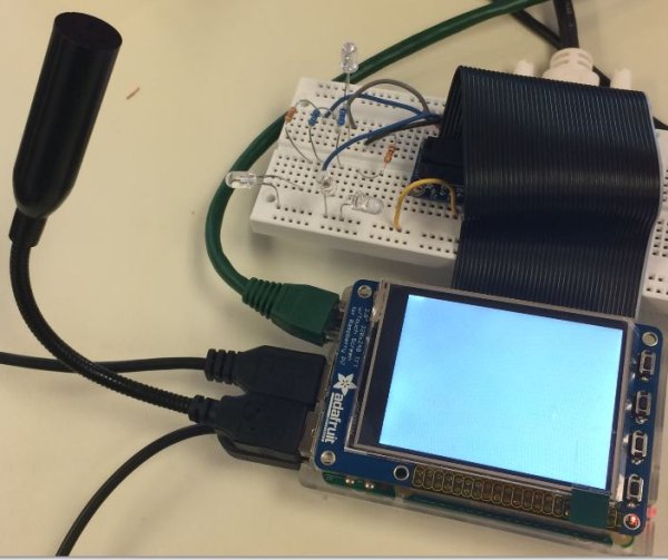
The project was initially tested with 4 LEDs instead of controlling speed and direction of the car as shown in figure 1.
The design was done following four stages:
Code Design
There are two separate parts for code designing. The first stage is to receive the voice from USB microphone attached to the raspberry pi and second is to read the text coming to the raspberry pi. In the first stage, the user is able to send voice command using the USB microphone attached to the raspberry pi. The bash script, “speech-recog.sh”, sends the human voice to the google API and google API analyzes the queries that was received by the user and converts the analyzed version of the user voice to the text and then the text will be the output from the “speech-recog.sh”. In order to read the text, we created a fifo file system and directed to the output of the bash script. The second stage is to read the fifo file through the python code. In the python code after reading from the fifo then we are able to output voltages to the 4 pins on the car, the 4 pins on the car which we already found. For the “forward” and “backward” movement we designed a PWM control signal which is coming from the two pins on the raspberry pi. Pin number 6, 26, 13 and 19 are for “right”, “left”, “forward” and “backward” respectively. For the “forward” direction the PWM has a range from 0-50 with the d efault duty cycle of 25 or almost half speed. In the “backward” direction, we set the default duty cycle to 22, a bit lower than the half speed. In this project, we also able to control the speed by saying “speed up” and “speed down”. For “speed up” we increase the duty cycle of the PWM signal for the “forward” direction every time by 3 and for “speed down” we decrease the duty cycle of the PWM signal for the “backward” direction every time by 3. In order to power up the raspberry pi we used a power bank to output 5V and 2A to the raspberry pi but we found that even though the battery provides enough voltage to power up the raspberry pi but after a while the raspberry pi was not able to generate enough power to feed the car.
The overall system design was shown in more details as shown in figure 3.

Voice Recognition:
The main part or the central part of the project is the software voice recognition. The voice recognition software that we use in the part project was created and developed by Steven Hickson. This voice recognition software is the most precise and potent software out there that works well with the Raspberry-Pi 2 model B. In this project we are using a separate speech recognition bash script which comes with the software. The bash script called “speech-recog.sh” which allow us to send voice command through microphone to the raspberry pi. The microphone capture our voice command and the bash script takes it then the bash script send our voice command to google for analyzing. The google API sends back the recognized voice and converted into a text and then the text which is the output of the bash script is directed to the fifo file system. The next step is to read from the fifo system. We read from the fifo through a python code that we created to output voltages from the 4 pins which is connected to the 4 pins on the car.
Hacking The Remote Car Control Signals:
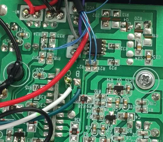
To serve the purpose of the this project, We bought a remote control car which runs on the radio control signals from the joystick. The car had three radio frequency channels and It can be controlled in Forward and Backward direction and also in Right and Left directions. Other than the four control signals, the car’s remote do not have any option to control the speed of the car. The reason why we bought this car is, we believed that, by hacking the car’s circuit to find the kind of car’s motor control signals generated in the car’s circuit for corresponding Remote control’s signals(Refer Diagram 1), we planned to generate the same kind of control signals from our Voice Recognition program running on the Raspberry pi. Each voice command recognized will generate the respective control signal for the Car’s command. We started dismantling the car to check the number of Motors the Car has. We found that the car has one motor for Forward and Backward Direction and one motor to control the direction Right or Left of the front wheels of the Car. We measured the input voltage being applied to the car and found that the Car’s Motor has an Input Voltage of 9V. With the help of online resources on hacking the same kind of Remote Car and by measuring the control signals one by one, we found the terminals were external control signals can sent to the Car’s circuit. We found that the Car’s control signals had a voltage of 3.3 V, which is same as that of the GPIO output voltage generated by the Raspberry Pi. We had a roadblock when the pins we found from the references as place to solder in the wires for the external signals turned out to be non ideal place to solder. We tried to figure out the alternate terminals where we can solder the wires easily and safely without destroying any components in the circuit. With the help of Professor Joe Skovira, We found that there is a current limiting resistors of value 1K in car’s circuit for all the control signals. We planned to remove the resistors and solder the external control wire from Raspberry Pi GPIO with our own current limiting resistor of value 1K. The car’s current limiting resistors were planned to be removed because of our speculation that the external signal may fire or break down some of car’s existing circuit, or the power loss for the control signal may occur in the other side of car’s circuit resulting in signal does not have enough power to drive the motor control. We started with Forward signal current limiting resistor. The current limiting resistors in the Car’s circuit turned out to be Surface mounted. This added additional difficulty because the resistor is so small and if careless the Car’s circuit may get damaged while removing. On Professor Joe’s advice, we used magnifying glass and small holders to carefully solder the current limiting resistors out of the Car’s circuit. Once we soldered out the current limiting resistors, with help of multimeter we measured the resistance between the terminals where current limiting resistor was soldered out and confirmed that the terminals are open circuit. We soldered external wire to the node where the resistor was soldered out and connected it to the output signal from Voice Command program of Raspberry Pi. The Car’s motor which was supposedly needs to run in forward direction did not run as expected. Later we figured out that the “Ground” connection to the Car’s circuit was not established. Once we connected the Car’s “Ground” to raspberry pi’s ground, The Car’s motor responded by running in forward direction. With this testing successful, we moved forward to remove all the other current limiting resistors of Left, Right and Backward signals in the same fashion as how we did for Forward signal and connected the external wires to it. Once we connected, we tested each signal by sending them a 3.3V voltage signal.
Speed Control using Pulse Width Modulation:
The RC’s remote does not have any controls to control the speed of the Car. Since, there is no speed control techniques already available in Car’s function, we decided to control the Speed of the motor by controlling the input voltage of the motor. The stepper motor control code we implemented as part of ECE 5990 lab gave us an Initial idea to build a Resistor Capacitor circuit whose input would be the PWM output signal from Raspberry pi. Output of the Resistor Capacitor circuit would be fed as the backward and forward signals of the Car. But, we realized that, the Car’s control signal is the one which gets the output of the Resistor Capacitor circuit, not the Input Voltage. So, using oscilloscope we checked the forward control signals generated from the Car’s inbuilt radio control and found out that it is a dc signal. Then as a next step, after we confirmed that all the signals are DC, we checked whether there is any inbuilt Resistor capacitor circuit in the Car’s Circuit in the path of forward and backward control signals. We found a resistor and capacitor connected in the car’s circuit connected parallelly, we planned to apply PWM signal directly to check whether it gives any speed reduction. As expected, the Car’s motor speed changed when applied with varied duty cycle. Logic was added to the Voice command code, such that for every “Speed Up” or “Speed Down” Command from the end user, the speed of the motor will also be controlled by increasing or decreasing the duty cycle of the PWM wave respectively.
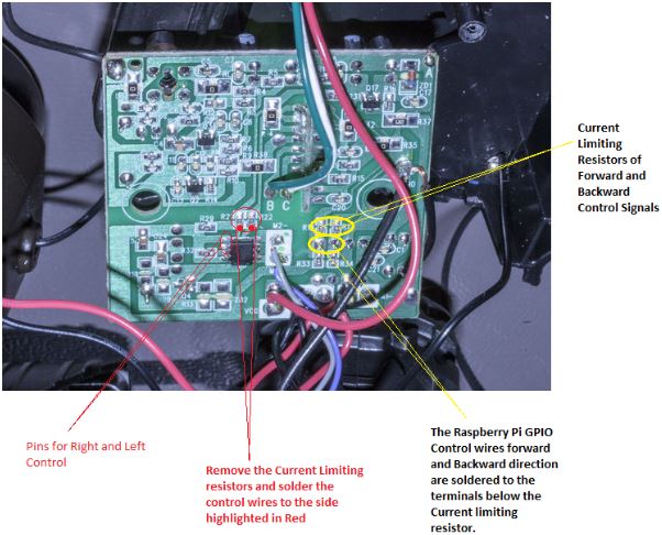
Figure 5. The Circuit diagram showing where the external control wires can be soldered.
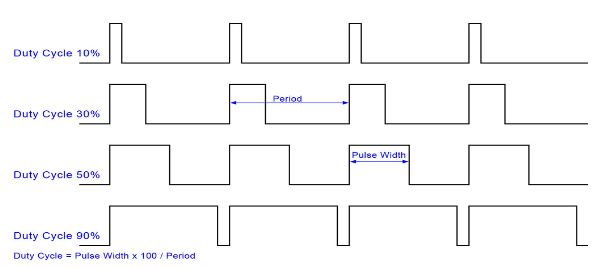
Figure 6. Pulse Width Modulation in which the output voltage can be controlled by changing the duty cycle

Results
Everything performed as planned, the Remote Car behaved according to the voice command sent by people. After the “Forward” command was sent, the car started to move forward with a constant default speed. When the “Left”, “Right”, “Backward”, “Speed up” and “Speed down” commands were sent to the Remote Car, it behaved with respect to these voice commands correctly.
Conclusions
The Remote Car was able to recognize and react according to the voice commands sent to it through the USB microphone. By training our program with training data for each of car’s control signal, we were able to achieve 75% consistency in controlling the Car. However there were also some drawbacks shown as below:
1. The Voice controlled Remote Car was able to recognize the voice commands but not as consistently as expected. Though the Voice recognition softwares have improved over time, the perfect voice recognition is still not available.
2. One more reason for the inconsistency might be the limiting amount of the training data, better performance in consistency could be achieved if more training data was made.
3. Sometimes after car was stopped or the first time the car was started, there might come out some noises from the Remote Car and the car didn’t move. In this case the reason might be either the low voltage controlled by PWM signal or the resistance of activate the wheels from standstill.
Future work
What would you explore if you had more time to work on the project?
1. Camera: In this case the camera is going to be used for recognizing and following a person
2. Panel on TFT Screen: Four software “arrows” will be designed on the TFT screen and one of them is going to show up when the corresponding command are recognized by the R-Pi on the Remote Car.
Appendices
A. Cost Details
|
Part Number |
Vendor |
Quantity |
Price |
Total Cost |
|
RC Car Crawler |
Amazon |
1 |
$37 |
$37 |
|
USB Microphone |
Amazon |
1 |
$10 |
$10 |
|
16 pack AA Batteries |
Walmart |
1 |
$12 |
$12 |
|
RPi 2 model B |
Cornell Lab |
1 |
$0 |
$0 |
|
PiTFT |
Cornell Lab |
1 |
$0 |
$0 |
B. Distribution of Work
| Ashkan Ravani | Xiaoyu Guo | Vishnu Govindaraj |
|---|---|---|
| Software Design | Software Design | Software Design |
| Hardware Hacking | Hardware Hacking | Hardware Hacking |
| Trouble shooting | Trouble shooting | Trouble shooting |
| Final Report | Final Report | Final Report |
| Webpage | Webpage | Webpage |
C. Code Listing
The three last files are the main files that runs the project. The zip file includes the whole program.
PiAUISuite.zip
speechRecogRun_final.sh
read_voiceCommand_final.py
speech-recog.sh
References
This section provides links to external reference documents, code, and websites used throughout the project.
Acknowledgements
We thank Professor Joseph Skovira and the lab TA for the debugging help and knowledge on Linux and Raspberry-Pi board they provided this semester.
Read more: Voice Controlled Car