
In the page, we introduce you to the open-source hardware and software that allows you to use OpenSense to analyze movements in real-time, show you how to assemble your own device, and provide information for you to customize the setup to a specific application.
- What is the OpenSenseRT System?
- How to Setup the Open-Source Software
- How to Assemble the Hardware
- Customizing the OpenSenseRT System to Track Specific Body Segments
- Using the OpenSenseRT System
- Learn More
What is the OpenSenseRT System?
The OpenSenseRT System is a project using open-source software and hardware to compute the motions of body segments based on inertial measurement unit (IMU) data using the processing power of a microcontroller worn on the body. The architecture can be customized to track specified body segments. The components are off-the-shelf and cost approximately $120 for base components and $20 for each tracked body segment. This page aims to help replicate the system for use in other studies. For full technical details, please read our paper. The hardware can be assembled with common hand tools and does not require coding or soldering. We’ve created a video tutorial to demonstrate the system and the setup process. Check out the example demonstrations video!
How to Setup the Open-Source Software
The open-source software uses an Ubuntu image which can be downloaded from our repository. This image contains the operating system and code that will run on the Rasberry Pi. Once downloaded, unzip the image file. Insert your microSD card into your computer using the SD card adapter. We will transfer the Ubuntu image to the microSD card using a free program called balenaEtcher. Install this software and open it. Select the image location that you downloaded, select the microSD card as the drive to install to, and click “Flash!”. Once this has completed, you can eject the microSD card and insert it into the Raspberry Pi. You have finished installing the software and are ready to assemble the hardware.
How to Assemble the Hardware
The OpenSenseRT System consists of hardware components including a Raspberry Pi microcontroller and associated parts, one IMU placed on each tracked body segment, velcro straps to attach the IMUs, and pre-made wires to connect the IMUs to the Raspberry Pi. Feel free to browse the full list of components with suggested vendor links when purchasing, but note that the number of IMUs and the other straps required to mount the IMUs will depend on which body segments you will be measuring. The bill of materials suggests vendors for components. The system was validated with the Adafruit ISM330DHCX IMU, but due to limited availability we have added support for the Adafruit LSM6DS33 and LSM6DSO32 IMUs (links provided in the bill of materials).
To help simplify assembly we have created a video tutorial rather than text instructions. Please follow the steps in the assembly video
Orienting the IMUs
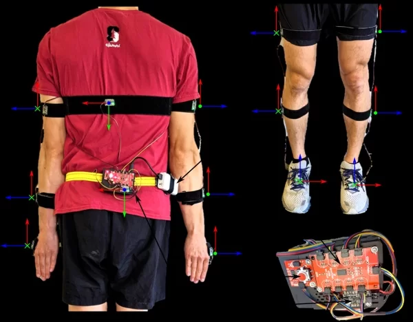
Once the Raspberry Pi and associated parts are assembled, it is important to double check the orientation of the IMUs on the body. This is necessary for proper calibration which will be discussed in more detail in the “Testing the System” subsection. The proper orientations for the sensors should follow the image below. The x, y, and z axes of the IMU correspond to the red, green, and blue vectors shown on the image. The axes are drawn on the IMU to help with this alignment.
Fig 1. The components and default IMU orientations of the OpenSense Real-time System. (A) An IMU on the pelvis is required and acts as the base in order to compute the relative orientation of other sensors. The OpenSense Real-time System accommodates a variable number of additional IMUs to customize which kinematics are measured. To monitor movement of the upper body, three IMUs may be placed on each arm (upper arm, forearm, and hand). An additional IMU can be placed on the torso. The orientation frame with axes shown in red, green, and blue are used to orient the x, y, and z axes defined on each IMU. These individual body frames should align with the world reference frames of the fore-aft, mediolateral, and vertical axes, while the subject’s joint segments are aligned in a neutral standing (or other known) position. (B) The lower-limb IMU placements also require the pelvis IMU as a base and include three IMUs on each lower limb, measuring the thigh, shank and foot. Any number of upper and lower limb IMUs can be combined and measured simultaneously. (C) A zoomed in view of the system components shows the microcontroller, battery, button (for starting and stopping recordings), IMU connector, and pelvis IMU.
Customizing the OpenSenseRT System to Track Specific Body Segments
We define the body segment tracked by each sensor by associating it with the number of the port it is plugged into. We provide a text file for defining sensors and associated body segments on the Raspberry Pi, which you can edit with the following instructions.
Accessing the file contents of the Raspberry Pi SD card
You can access files on the Raspberry Pi SD card by inserting it into a computer. The method of accessing these files depends on your operating system. If your operating system is Linux or Mac then you should be able to open and edit any file on the SD card. For Windows you will need to download a program to read and edit the files. We suggest Ext2Fsd, which is free and has instructions on how to use it.
Defining which body segments to track with the IMU sensors
We will now define which sensors are tracking which body segments. Open the settings.txt file in the RealTimeKin folder on the Raspberry Pi SD card. The first line lists all body segments that can be tracked by the system. The second line defines which port an IMU used to track that body segment. For example, the first body part is Pelvis and the first number on the second line should be set to whichever port the IMU you will be using to track the Pelvis is plugged into. If a body segment is not tracked, then input the number 9.
You can connect two sensors to each port by soldering the jumper on the back of the IMU, which changes the address of that IMU. To define which port this soldered sensor is connected to, simply add a ‘b’ to the number. For example, port 1b. This is useful for simplifying the wiring. For example, you can plug an IMU used to track the thigh into port 1, and then plug an IMU with a soldered jumper used to track the shank into the other end of the thigh IMU and define it as port 1b. Now you have one wire going from the Raspberry Pi to the thigh IMU and then to the shank IMU. See the video instructions for more details.
The third line of the settings.txt file is the computation frequency, the maximum frequency that can be computed depends on how many IMUs are in use. The recommended frequencies based on the number of IMUs is detailed in the research paper. The fourth line denotes whether the system will run in real-time using the “online” mode or simply save the raw IMU data for computing later in the “offline” mode. The fifth line defines the name of the folder where the recorded kinematics will be saved. The sixth line defines what the maximum recording length can be before the recording is automatically ended. The seventh line acts as a way to calibrate the system for a new IMU configuration. The first time a new IMU setup is used, the word “calibrate” should be added to automatically remove the bias in measurements from the gyroscopes. This line will be automatically deleted from the file after calibration is complete, so the system does not need to be recalibrated for each use.
Using the OpenSenseRT System
The OpenSenseRT System is designed to be simple to use for estimating kinematics. The recorded motion can be started and stopped using a button. This relies on the user starting in an initial calibration pose for each recording. The Raspberry Pi can record more than 100 hours of motion, one battery providing 6 to 7 hours of recordings.
Calibration
In order for the OpenSenseRT System to understand the starting pose of the wearer, we use a default position to begin each recording. This is a standing position with the arms at the sides and thumbs facing away from the body as previously shown in Fig. 1.
The first time a new settings file is run the system will calibrate the gyroscopes for that particular arrangement of IMUs. We suggest that the first time you connect the IMUs and turn the system on you leave it stationary on a table for the gyroscope calibration. The LED will pulse for ten seconds during this calibration before returning to the normal mode of operation.
Instructions for general use
The OpenSenseRT System indicates information to the user with an LED and can receive input from a button. On startup the LED will begin to blink when the System is ready to be calibrated as previously discussed. The user should assume the calibration position and then press the button to initiate the recording. The LED will become a solid red light while recording. Pressing the button again will stop the recording.
Visualizing the saved files
The motion files are saved numerically for each run with the raw IMU data in a numpy ‘.npy’ file, the kinematics motion data in a ‘.mot’ file, and the timestamps of each sample in a ‘.npy’ file. The motion files can be visualized using OpenSim. See the introductory information for setting up OpenSim and loading a motion file.
Recording with an external signal trigger
In order to allow the device to start and stop recording in sync with other sensors an external signal can be used in addition to the button. Setting up wiring to the Raspberry Pi will require some custom changes to the hardware depending on your experimental setup. The external signal should be connected to the Raspberry Pi pin BCM 16. Your experimental setup should apply 3.3V to this pin to start recording, and maintain 3.3V until you wish to stop recording. All other times you should apply 0V to this pin.
Debugging errors
We suggest testing your initial setup by assembling the device as previously discussed and performing a short data collection and visualizing the result to ensure the system is performing as expected. Errors in the system are challenging to debug due to the use of hardware and software components. See the instructional video for more information.
Learn More
The current version of the OpenSenseRT System is our first step in open-sourcing both hardware and software components to provide accurate, low-cost, and wearable IMU-based biomechanics tools to the research community. This system can be customized for specific research applications by modifying the provided Python code. The main code directory is the Github repository, which contains the Python files that can be modified. While we currently won’t be able to support customized projects, we’ve provided the additional information about the system to allow you to access and modify the code as needed. These steps assume you have completed the previous setup instructions.
Connecting to the Raspberry Pi
The Raspberry Pi uses an Ubuntu operating system based on the linux terminal, which means it does not have a GUI that you would normally see in everyday desktop or laptops. We recommend you become familiar with navigating the Ubuntu command line before proceeding.
In order to interact with code on the Raspberry Pi you will need to connect an external monitor and USB keyboard or SSH over a WIFI network. If you are unfamiliar using SSH then we recommend using a monitor and keyboard. Note that the Raspberry Pi 4 requires a micro-HDMI connector. For additional details see this Raspberry Pi Introduction. Once you have connected your monitor and keyboard, turn on the Raspberry Pi and you will see commands scroll across the screen during startup.
Finding the IP address for an SSH connection
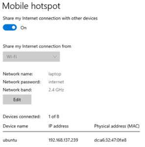
To SSH to the Raspberry Pi we have predefined a WIFI network it will connect to. You will need to first set up WIFI hotspot using a laptop or desktop. See sample instructions for Linux, Windows, and Mac operating systems. Set the network name, password, and bandwidth as follows:
- Network name: laptop
- Network password: internet
- Network band: 2.4 GHz
Once you have set these values, turn on the Raspberry Pi. After approximately one minute, you will see the IP address of the Raspberry Pi. An example is shown in the figure below. I’ve found that if I am connected to a VPN then the Device Name shows up as Unknown and I am able to connect until I stop the VPN.
Logging in to the Raspberry Pi
On startup, use the following login information:
- Username: ubuntu
- Password: realtimekin
Customizing the WIFI connection
You can change the wifi connection by going to the /etc/netplan/ directory and modifying the file. Simply change the wifi network name and password in this file, but do not change the spacing or any other contents! We recommend using the installed vim editor by typing “sudo vim filename”. Once this has been changed run the following commands to confirm the changes and then reboot the Raspberry Pi to finalize changes. Add the line “country=US” to the top of this netplan file if you will be using a 5 GHz wifi connection rather than 2.4 GHz.
sudo netplan -debug trysudo netplan -debug generatesudo netplan -debug applysudo reboot |
Further Customization
For additional modifications I recommend you look at the Raspberry Pi webpage and forums and look at the configuration file for the Raspberry Pi: /boot/firmware/config.txt
Source: Wearable and Real-time Kinematics Estimates with OpenSense