1. INTRODUCTION
With the advent of e-commerce, the demand for products has increased and the companies need large inventory and require handling large volumes on a daily basis. This includes a lot of labor- intensive tasks like storing, moving, scanning, inspecting, delivering, and many more. For better efficiency, increasing number of warehouse and distribution centers are moving towards automation in varying degrees, from semi-autonomous to completely autonomous systems, based on the demand.
Robotic handling systems are increasingly used in warehouses and distribution centers as they provide flexibility in managing varying demand requirements and can work 24/7.
In this project, a robotic arm is used to transfer packages from a conveyor and load it onto a inhouse transportation bot for stocking.

II. WORKING
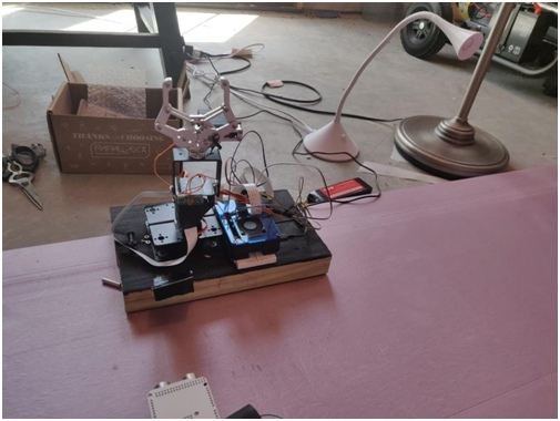
This is an automated pickup and transport system, where the 2 DOF robotic arm (shown in Figure
2) can rotate about the z-axis & the x-axis and has a gripper. The transportation bot (shown in
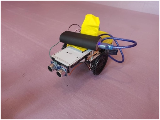
Figure 1) has an ultrasonic sensor mounted on it to detect, its distance from, the docking station. Once it is near the station, the vehicle turns 180 degrees while sending a notification to the arm informing the arrival. At reception, the arm initially aligned with the z-axis, rotates 90 degrees towards the conveyor, to pick up the cargo from it with the help of a gripper. Once it picks the cargo, the arm rotates -90 degrees aligning itself back with the z-axis (gripper pointing upwards). The arm then starts rotating about the z-axis as it searches for the transportation vehicle, using OpenCV and PiCamera. Once it discovers the transportation bot that is stationed opposite the conveyor, the arm further rotates the arm -90 degrees, towards the bot, about the x placing the gripper on top of the pickup bot. Later, the gripper opens to place the cargo on the bot, and then gives a (Bluetooth) signal to the same indicating the loading, as it moves back to the initial position. Once the transportation vehicle receives this notification, it starts moving away from the docking station towards the desired stocking location.

III. LOW PASS FILTER
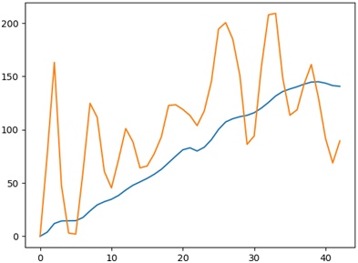
We used a Low Pass Butterworth filter to filter out the high-frequency changes in the camera read x-y-z data. We are creating a vector out x-y-z values and applying this filter to it. After applying the filter, we are taking the average values of the last 20 elements of the vector so as to reduce the noise and smooth the graph, therefore getting a more accurate position of the ball from the PiCam.

In the Figure 3, the orange line is raw data (which is very noisy and fluctuating a lot) and the blue line is filtered bata which is smooth.
IV. ELECTRONICS
Servo: a total of 5 servo motors are used in the project. 2 for driving the transportation vehicle (differential drive). 3 are used to control the joints of the robotic arm.
Ultrasonic Sensor: An ultrasonic sensor measures the distance to an object using ultrasonic waves. The transmitter in the sensor emits short, high-frequency sound pulses at regular intervals which propagate in the air and are reflected back as echo signals to the receiver when they strike an object. The distance is computed by measuring the time span between emitting the signal and receiving the echo (called Time of flight). It is mounted on the mobile robot and used for path planning and detection Bluetooth: HC06 mounted on Arduino is used to communicate serially with the inbuilt Bluetooth module of the Raspberry pi.
Pi-Camera: A camera mounted on one of the joints of the robotic arm is used to track the transportation vehicle stationed somewhere in the docking station.
V. CIRCUIT

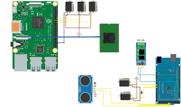
As we can see in the Figure 4 we have used three servos in the raspberry pi.
Raspberry pi only has two PWM pins, so we have written our own PWM servo code to make three servos run,
Pi cam is attached to the raspberry pi as shown above. The camera finds the ball using OpenCV and locks the position of the arm.
Arduino has a total of four components attached to it as shown in the figure above. Two servos, one ultrasonic sensor, and one HC-06 Bluetooth module. Which is used to run the cargo bot?
V. CODE
VI.I. Arduino Code:
#include <Servo.h>
Servo left;
Servo right;
const int GNND = 4; const int GNDD = 35; const int echo = 37; const int trig = 39; const int VCCC = 41;
float invcmCosnt = (2*1000000)/(100*344.8); //cmDist=rawTime/invcmCosnt void setup() {
Serial.begin(9600); Serial3.begin(9600);
left.attach(3); // attaches the servo on pin 9 to the servo object right.attach(5);
pinMode(trig, OUTPUT); pinMode(echo, INPUT); pinMode(GNND, OUTPUT); pinMode(GNDD, OUTPUT); pinMode(VCCC, OUTPUT);
digitalWrite(VCCC, HIGH); digitalWrite(GNND, LOW); digitalWrite(GNDD, LOW); pinMode(LED_BUILTIN, OUTPUT);
left.write(114); right.write(74);
}
void loop() {
float rawTime, cmDist; digitalWrite(trig, LOW); delayMicroseconds(2); digitalWrite(trig, HIGH); delayMicroseconds(5); digitalWrite(trig, LOW); rawTime = pulseIn(echo, HIGH); cmDist = 100;
while(cmDist > 4){ digitalWrite(trig, LOW); delayMicroseconds(2); digitalWrite(trig, HIGH); delayMicroseconds(5); digitalWrite(trig, LOW); rawTime = pulseIn(echo, HIGH); cmDist = rawTime/invcmCosnt; Serial.println(cmDist);
}
Serial.println(“Out”); Serial3.println(“s”); left.write(94); right.write(94); delay(1000); left.write(114); right.write(114); delay(1700); Serial.println(“Turned”); left.write(94); right.write(94); Serial.println(“Stopped”); while(1){
if(Serial3.read()=='f'){ break;
}
}
left.write(114); right.write(74); delay(2500); left.write(94); right.write(94); while(1){
}
}
VI.II. Raspberry
At the Raspberry end, one needs to connect the Raspberry Pi to the HC-06 Bluetooth Module using the following commands to first find,
$ hcitool scan # Can be skipped if the MAC ID of the Bluetooth is known and is available
And then connect to the required Bluetooth using the right MAC ID:
$ sudo rfcomm connect hci0 xx:xx:xx:xx:xx:xx
If this executes successfully, then the Bluetooth is connected.
import the necessary packages from collections import deque
from imutils.video import VideoStream import numpy as np
import argparse import cv2 import imutils import time import timeit
from scipy import signal import matplotlib.pyplot as plt
import RPi.GPIO as GPIO
import serial
GPIO.setmode(GPIO.BCM) GPIO.setup(12, GPIO.OUT) # Gripper GPIO.setup(13, GPIO.OUT) # Rot_x GPIO.setup(16, GPIO.OUT) # Rot_z
rotz = 16
rotx = GPIO.PWM(13, 50) gr = GPIO.PWM(12, 50)
blue = serial.Serial(“/dev/rfcomm0”, baudrate=9600) print(“Bluetooth connected”)
def duty(angle):
return angle * 5 / 90 + 2.5
def search(angle=90, add=1): servo_pwm(rotz, duty(angle), 50) ap = argparse.ArgumentParser() ap.add_argument(“-v”, “–video”,
help=”path to the (optional) video file”) ap.add_argument(“-b”, “–buffer”, type=int, default=64,
help=”max buffer size”) args = vars(ap.parse_args())
xn = np.zeros([500]) xm = np.zeros([1])
greenLower = (20, 20, 53)
greenUpper = (64, 255, 255)
pts = deque(maxlen=args[“buffer”])
if a video path was not supplied, grab the reference # to the webcam
if not args.get(“video”, False):
vs = VideoStream(src=0).start()
otherwise, grab a reference to the video file else:
vs = cv2.VideoCapture(args[“video”])
allow the camera or video file to warm up time.sleep(2.0)
while True:
if angle == 125:
add = -5
elif angle == 35:
add = 5 angle += add
servo_pwm(rotz, duty(angle), 10) time.sleep(0.01)
grab the current frame frame = vs.read()
handle the frame from VideoCapture or VideoStream frame = frame[1] if args.get(“video”, False) else frame
if we are viewing a video and we did not grab a frame, # then we have reached the end of the video
if frame is None:
break
resize the frame, blur it, and convert it to the HSV # color space
frame = imutils.resize(frame, width=600) blurred = cv2.GaussianBlur(frame, (11, 11), 0)
hsv = cv2.cvtColor(blurred, cv2.COLOR_BGR2HSV)
construct a mask for the color “green”, then perform # a series of dilations and erosions to remove any small # blobs left in the mask
mask = cv2.inRange(hsv, greenLower, greenUpper) mask = cv2.erode(mask, None, iterations=2)
mask = cv2.dilate(mask, None, iterations=2)
find contours in the mask and initialize the current # (x, y) center of the ball
cnts = cv2.findContours(mask.copy(), cv2.RETR_EXTERNAL, cv2.CHAIN_APPROX_SIMPLE)
cnts = imutils.grab_contours(cnts) center = None
only proceed if at least one contour was found if len(cnts) > 0:
find the largest contour in the mask, then use
it to compute the minimum enclosing circle and # centroid
c = max(cnts, key=cv2.contourArea)
((x, y), radius) = cv2.minEnclosingCircle(c) M = cv2.moments(c)
center = (int(M[“m10”] / M[“m00”]), int(M[“m01”] / M[“m00”])) # only proceed if the radius meets a minimum size
if radius > 10:
draw the circle and centroid on the frame, # then update the list of tracked points cv2.circle(frame, (int(x), int(y)), int(radius),
(0, 255, 255), 2)
cv2.circle(frame, center, 5, (0, 0, 255), -1)
xn = np.delete(xn, 0) xn = np.append(xn, x) fs = 300
fc = 1 x_old = x
w = fc / (fs / 2)
b, a = signal.butter(5, w, ‘low') output = signal.filtfilt(b, a, xn) x = np.average(xn[480:500]) print(x, x_old)
xm = np.append(xm, x) if abs(x – 300) < 20:
break
update the points queue pts.appendleft(center)
for i in range(1, len(pts)):
if either of the tracked points are None, ignore # them
if pts[i – 1] is None or pts[i] is None:
continue
otherwise, compute the thickness of the line and # draw the connecting lines
thickness = int(np.sqrt(args[“buffer”] / float(i + 1)) * 2.5) cv2.line(frame, pts[i – 1], pts[i], (0, 0, 255), thickness)
show the frame to our screen cv2.imshow(“Frame”, frame) key = cv2.waitKey(1) & 0xFF
if the ‘q' key is pressed, stop the loop if key == ord(“q”):
print(xn) print(xn.shape) plt.plot(xm, label='x') plt.show()
break
if not args.get(“video”, False): vs.stop()
otherwise, release the camera else:
vs.release()
close all windows cv2.destroyAllWindows() return x, add
def servo_pwm(pin, duty, pulse): on = 20 * duty / 100000
off = -on + 20 / 1000 for i in range(pulse):
GPIO.output(pin, GPIO.HIGH) time.sleep(on) GPIO.output(pin, GPIO.LOW) time.sleep(off)
def grip(angle=90):
servo_pwm(rotz, duty(angle), 100) rotx.start(duty(90)) gr.start(duty(100))
time.sleep(1) rotx.ChangeDutyCycle(duty(0)) time.sleep(1) gr.ChangeDutyCycle(duty(180)) time.sleep(0.5) rotx.ChangeDutyCycle(duty(90)) time.sleep(0.5)
def drop(): rotx.ChangeDutyCycle(duty(180))
time.sleep(1) gr.ChangeDutyCycle(duty(100)) time.sleep(1) rotx.ChangeDutyCycle(duty(90)) time.sleep(0.5)
def done():
done = “f”
done = done.encode() blue.write(done)
try:
while True:
data = blue.readline() # data = data.decode()
print(type(data), data) # if data != “s”:
print(“didn't”) # continue
else: print(“found s”) grip(80)
x, add = search(80, 5) drop()
done()
except KeyboardInterrupt: GPIO.cleanup() print(“Quit”)
VII. CONCLUSION
In this project, we implemented a cargo handling system for warehouse automation. A Robotic arm picks up items from a conveyor belt, searches for the transportation vehicle using a camera mounted on it, loads the order onto the vehicle after which the transportation vehicle then takes the goods to the required location for further processing. Warehouse automation is becoming more and more common in both big and small companies due to the growing demands of customers and growth in e-commerce. The Goods to People (GTP) is a newer emerging trend where goods are moved to the workers, rather than workers to items. According to Nathan Busch, associate consulting engineer at Bastian Solutions Inc., “The throughput rates of GTP systems are typically quite a bit higher than traditional manual operations. This allows companies to reduce their overall operating and order fulfillment costs while improving throughputs and service levels.” Mobile robotics has now become a crucial part of this as the items are searched for, picked up, and then taken to their respective processing sites. Future scope of this project was broadly considered for a fully autonomous warehouse system, where the items that are to be stocked can be separated by another system and the above presented system can transfer the goods from the conveyor to the stocking bot, that further finds an optimal path to the desired stocking location and stocks the goods. This demonstration presents that the mentioned system can be implemented in parts for the benefit of smaller businesses; therefore, combining the manual and robotic operation for an increased throughput and improved performance.
Source: WEARHOUSE DISTRIBUTION

